What Is a Pin-Compatible IC and Why It Matters
What is a pin-compatible IC and why it matters: an IC with the same pinout and package as another, so it mounts on the same footprint, and how it is verified.
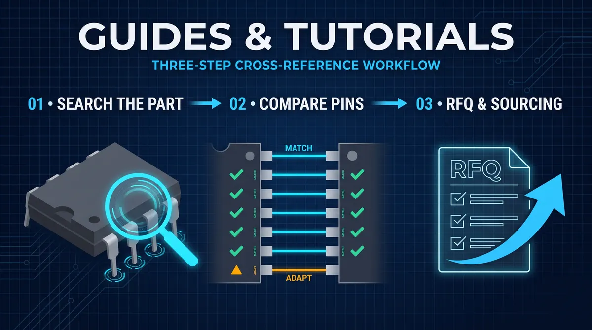
What is a pin compatible ic and why does the answer matter enough to define an entire sourcing practice? A pin-compatible IC is an integrated circuit that places the same functional signals on the same numbered pin positions inside the same physical package as another integrated circuit, so it can be soldered onto the same printed circuit board footprint in place of the original without a board re-layout. The term is used across the electronics industry interchangeably with pin-to-pin compatible, and it describes the highest-value form of component substitution short of an identical part from the same manufacturer, because a pin-compatible alternative preserves the board, the assembly process, and most of the surrounding design while changing only the component itself. Buyers and engineers care about this definition because a pin-compatible part is the shortest path out of an end-of-life notice, a component shortage, a price shock, or a single-vendor supply chain risk, and it is the exact wording that defines what this site does: helping buyers find and source parts that fit the same pins. This article defines the term precisely, explains its grades, shows which well-known part families are pin-compatible, and lays out the checks that turn a claim of compatibility into a verified fact.
The definition has three parts, and all three must hold. The first is the package: the candidate must share the same package code, such as DIP-8, SOIC-8, TO-220, or TSSOP-20, so the physical body and the pad geometry match the footprint on the board. The second is the pinout: each pin position on the candidate must carry the same function as the corresponding pin position on the original, from the power pins through every input and output. The third is the electrical behavior: the candidate must operate within the same supply range and deliver functionally equivalent output performance for the circuit it is replacing, because a PCB that fits means nothing if the signals meet the wrong levels or timings. When all three hold, the part is pin-compatible, and the remainder of this article shows how engineers and procurement professionals verify each of the three before they ever change a BOM line.
What Is a Pin-Compatible IC in the Compatibility Hierarchy
A pin-compatible IC is one level in a well-understood compatibility hierarchy that electronics professionals use to assign a price, a risk, and a timeline to every substitution decision. At the top sits the drop-in replacement, a part that shares the package, the pinout, the electrical behavior, and usually the firmware or software behavior, so it swaps directly with no board change and no code change. Immediately below it is the pin-compatible part, which shares the package and the pinout and is electrically equivalent for the application, but may need minor software adjustment when the part is a digital or microcontroller device. Next comes footprint-compatible or package-compatible, where the pad footprint matches but the pin functions differ, so wires or short jumpers are needed to bridge the difference. Below that sits the functional equivalent, a part that does the same job in a different package or pinout and therefore demands a board redesign to use. The hierarchy matters because each level downward multiplies the cost and the risk of the substitution, and pin-compatible sits at the pragmatic center, delivering most of the value of a drop-in with far wider parts availability.
The practical consequence of the hierarchy is that pin-compatible is the realistic goal for most substitutions, not drop-in. True drop-in parts are only guaranteed when a manufacturer produces the same silicon in different temperature grades or when an authorized second-source agreement exists, both of which are rarer than buyers would like. But the electronics market is full of parts designed to the same pinout by multiple manufacturers, and those are pin-compatible even when the internal silicon differs: the classic 78xx series of three-terminal regulators, the 555 timer, and a large share of the 7400-series logic family are all distributed across many vendors in functionally identical pinouts. For those families the answer to what is a pin compatible ic is not an abstract definition but a concrete stock of parts, any one of which drops into the existing board and works. Positioned that way, pin compatibility is both a definition and a market, which is precisely why a buyer frustrated by an end-of-life notice searches for the phrase instead of surrendering to a redesign.
How pin-compatible compares to drop-in in practice
The practical difference between drop-in and pin-compatible is best captured by the examples engineers meet every week. A 7805 linear regulator made by one vendor and a 7805 from another vendor of the same pinout and output voltage are effectively drop-in for most boards, because the interface to the rest of the circuit is identical and no software exists to change. A microcontroller like the STM32F103 and a domestic alternative like the GD32F103 share the LQFP48 pinout and are pin-compatible and largely code-compatible, but moving between them still involves checking the register map and the firmware build, which makes the swap pin-compatible rather than a thoughtless drop-in. In both cases the board does not change, and that is the defining shared property: the moment the board is untouched, the substitution belongs to the top two grades, and the remaining work is either nothing or a software-and-verification task. Choosing the accurate grade is also a professional discipline, because labeling a part drop-in when it is only pin-compatible sets an expectation that the oxide layer of a BOM change will not tolerate, while labeling a pin-compatible part non-substitutable wastes the best option available.
What Is a Pin-Compatible IC in Terms of the Datasheet
Read across a datasheet, the answer to what is a pin compatible ic becomes a three-page checklist, and datasheet literacy is the skill that lets an engineer confirm compatibility instead of trusting a part number. The first datasheet page to consult is the pin configuration diagram, which numbers every pin and names its function, and the second is the ordering information, which lists the package code for the exact device ordered. Compatibility is decided by overlaying the original part's pin diagram onto the candidate's pin diagram and checking every position: the power pin, the ground pin, any reference pins, the control and enable pins, and every signal input and output. The third page is the absolute maximum ratings and the recommended operating conditions, which confirm that the candidate tolerates the voltages and how the original design drives. The fourth is the electrical characteristics over the operating temperature range, which confirm that the candidate's output levels, output current, timing, and accuracy meet the receiving circuit's requirements. A review that covers these four pages is a complete compatibility check, and it is the same review a qualified supplier performs before it lists a part as an alternative.
The most instructive part of the datasheet comparison is the pin with a different label, because that is where compatibility is won or lost. Power pins and ground pins are dictated by the package standard and almost always match, but vendors diverge on the functional pins: one part may place an output-disable on a pin where the other places a second independent output, or one datasheet labels a pin no-connect where the other assigns a function that a jumper must bridge. A single functional pin that differs moves the part from pin-compatible to footprint-compatible, so the pin-by-pin comparison cannot skip any position, including the pins the original design leaves unused. The discipline of checking unused pins matters because a later revision of the board may use them, and because a candidate that claims compatibility while a function sits on the wrong pin will fail the moment anything drives that pin. Datasheet comparison is the layer where the abstract definition meets the physical part, and it converts a promise on a component listing into a documented fact.
Reading a pin compatibility table from the manufacturer
Manufacturers formalize the datasheet comparison into pin compatibility tables, and learning to read them speeds every substitution. A vendor that sells a family of parts on one pinout, such as a series of microcontrollers spanning different flash sizes and speed grades, publishes a table that states which devices share the pinout, which sockets accept which packages, and which devices require firmware changes between rows. The table usually accompanies a migration or application note that explains the differences, and it is the most authoritative compatibility document available because it comes from the vendor that owns the silicon. When the vendor states that two parts are pin-compatible, the remaining work is the electrical and software review, and when the vendor prints a compatibility matrix with footnotes, each footnote is typically a specific pin behavior, a peripheral difference, or a firmware change that the design must respect. Using these tables converts a search into a decision, and it is the first stop for anyone replacing a microcontroller, a processor, a memory, or any device whose pinout belongs to a documented family.
Which Well-Known ICs Are Pin-Compatible
The concept of pin compatibility becomes concrete when it is mapped onto familiar part families, and a practical answer to what is a pin compatible ic is delivered by walking the most famous examples. The 78xx series of positive fixed output-voltage regulators is the archetype: a 7805, a KA7805, an L7805CV, and a host of pin bundles from vendors all share the same three-pin TO-220 or SO-8 layout and the same 5-volt output, so they are interchangeable on a standard footprint. The 555 timer family follows the same pattern, with a shared DIP-8 and SOIC-8 pinout for the NE555 and its variants. The 7400-series logic family is pin-compatible across logic families at the same function number in many cases, so a 74HC595, a 74HCT595, and their vendor variants share the SOIC-16 footprint and the same pin functions with speed- and level-related differences. The LM358 and LM324 dual and quad op-amp pinouts are shared across a wide range of vendors, and the STM32F103 pinout is deliberately reproduced by domestic manufacturers such as GigaDevice's GD32F103 and Artery's AT32F403A, which target both pin and software compatibility. Each of these families is a working answer to the definition, and each is a family this site sources as pin-compatible alternatives.
The reasons these families became pin-compatible are worth understanding because they predict which other parts will also be interchangeable. The first reason is standard-setting by a dominant vendor: Texas Instruments and the classic manufacturers defined pinouts for regulators, timers, op-amps, and logic that became de facto standards, so every later vendor that wanted a share of the market built to the same pins. The second reason is the connector standard, where interface parts like RS-232 transceivers and RS-485 drivers gradually standardized around shared pinouts. The third reason is deliberate second-sourcing, where a manufacturer, often in China, designs a pin-compatible and often code-compatible alternative to a mainstream MCU or power part specifically to capture the replacement market, the exact pattern behind the STM32-compatible domestic MCU families. A buyer who knows a family's pinout is standardized can predict that alternatives will exist and can go straight to cross-reference tools, while a buyer facing a proprietary pinout knows the search will be harder and should start with the manufacturer's own alternate-part table instead.
A table of classic pin-compatible families
| Family | Typical part | Shared package(s) | What is pin-compatible | Notes |
|---|---|---|---|---|
| 78xx regulators | LM7805, KA7805, L7805CV, AMS1117-5.0 (SMD only) | TO-220, TO-252, SOT-223, SOS-8 | Identical 3-pin layout, same output voltage | Confirm input range, dropout, current before swap |
| 555 timers | NE555, SA555, SE555, NE556 | DIP-8, SOIC-8 | Same 8-pin layout and trigger/output behavior | NE556 is a dual in a 14-pin package, not pin-compatible with NE555 |
| 7400 logic | 74HC595, 74HCT595, 74LS595 | SOIC-16, DIP-16 | Same 16-pin functions across families | Family differences: speed, input thresholds, supply |
| Dual op-amps | LM358, LM2904, LM393 | SOIC-8, DIP-8 | Same 8-pin dual op-amp layout | Watch output swing, supply, and audio performance |
| Quad op-amps | LM324, LM2902 | SOIC-14, DIP-14 | Same 14-pin quad layout | Same caveats as the dual family |
| STM32-compatible MCUs | STM32F103C8T6, GD32F103C8T6, AT32F403A | LQFP48 | Same LQFP48 pinout, aim for code compatibility | Verify register map and firmware before wholesale switch |
| RS-232 transceivers | MAX232, SP232, HIN232 | SOIC-16, DIP-16 | Same charge-pump transceiver pinout | Check capacitor values and data rate |
| Motor drivers | ULN2003 (Darlington), compatible arrays | SOIC-16, DIP-16 | Same 7-channel Darlington pinout | ULN2803 has 8 channels, different pin count |
| Buck regulators | LM2596, LM2576 and alternatives | TO-263, TO-220, SOP-8 | Same switching-regulator pinout in some vendor lines | Verify switching frequency and inductor design |
Why Pin Compatible ICs Matter for Procurement and the Supply Chain
For procurement teams, a pin compatible IC is the single most valuable answer to a supply problem because it decouples the component from the board. When a part goes end-of-life or a shortage drives a tiny distributor price to absurd levels, the team has two honest choices: redesign the board or qualify a pin-compatible replacement. Redesign is measured in months and in engineering hours, it risks the reliability of a shipping product, and it can trigger new certifications or customer re-approvals that stretch even longer, so any alternative that keeps the board intact has enormous leverage. A pin-compatible part keeps the assembly the same, which keeps the test fixtures the same, keeps the pick-and-place program the same, and keeps the field hardware the same, so the only new work is qualifying the component itself. That leverage is why multinational buyers maintain second-source programs and why the phrase second source is taught in procurement courses as a core security strategy. When a design is standardized on a well-known pinout, the buyer can even select a pin-compatible sole- or multi-vendor strategy from the start, so the supply chain never depends on one manufacturer.
The sourcing dimension of pin compatibility has its own rules, and they are about verification and availability rather than price alone. A supplier that lists a part as pin-compatible should be able to show the datasheet comparison and, for a qualified alternative, the certificate of conformance and the traceability documents that prove the part is authentic and matches the claim. Availability comes in the real quantities a buyer needs, at a stated MOQ and lead time, in the packaging the assembly line uses, and that set of facts is exactly what a pin-compatible replacement supplier is organized to provide: the cross-reference data and the stock. For obsolete and hard-to-find parts, the same rules apply but the supplier becomes critical, because only a specialist that holds legacy inventory or buys end-of-life stock can deliver a pin-compatible part when the mainstream channel has none. In procurement terms, pin compatibility is not a technical curiosity, it is the structural condition that turns a supply emergency into a routine sourcing task, and that is why the term appears in every serious buyer's vocabulary.
How pin compatibility reduces supply chain risk
The risk arithmetic of supply chains makes pin compatibility a headline strategy. A board built around a single-sourced part has a single point of failure, and the moment that part meets an end-of-life notice or a market shortage, the entire product line is exposed. A board built on a pin-compatible standard, by contrast, can be sourced from two or three vendors that never share the same shortage schedule, which is the essence of a second-source strategy. The buyer who qualifies a pin-compatible alternative keeps the original as a primary source, uses the alternative as a negotiating and security lever, and can switch production between them on the same board and the same test program. The data supports the discipline: component lifecycle reviews catch the end-of-life notices early, and an early catch is the difference between qualifying a replacement at leisure and scrambling during a halt. A supply chain that treats pin compatibility as a design decision, rather than as an emergency tactic, builds the room to maneuver into the product from the start, and the buyers who run that strategy describe the same outcome from different industries: the board never changed, the line never stopped, and the part was the only thing that moved.
When a Pin Compatible IC Is Not Quite Enough
Pin compatibility answers the physical question, but the physical question is not always the whole question, and responsible engineers know when pin-compatible is not enough. The first case is electrical, where a candidate fits the pins and the package but violates a parameter the design depends on: a lower maximum input voltage, a higher dropout, a slower slew rate, a longer propagation delay, or a temperature grade below the product's ambient range. The second case is timing and interface, where the receiving circuit has a timing budget the candidate does not meet, so an apparently clean substitution corrupts data at speed or fails across temperature. The third case is software for digital parts and microcontrollers, where a pin-compatible MCU with a different register map, peripheral set, or core variant will not run the existing firmware without porting, and the porting effort is exactly the difference between pin-compatible and the top grade. None of these cases means the part is unusable, but each one changes the project scope, so the honest label matters: a pin-compatible part that needs a firmware milestone is a pin-compatible part with a software task attached, and the buyer and the engineer should plan for that task before committing to it.
The professional response to these cases is to check before believing and to document what the check found. Run the three-layer review, package, pins, and electrical behavior, against the datasheets, and for digital parts add the firmware bring-up test, using the migration notes from the vendor where the family publishes them. Record the absolute maximums, the operating range, and the measured signals, and keep the record with the part change notice so that any future reviewer sees exactly which parameters were compared. What this produces is a compatibility statement with an evidence trail: the part is pin-compatible, verified against these parameters, and here is the load that proves it. That evidence is what allows an ISO-managed organization to change a BOM without drama and allows a supplier to stand behind the alternative it ships, and it is the completion of the definition, which began as a sentence about pins and ends as a documented engineering decision.
How to Compare Two Pinouts: A Worked Example
Comparing two pinouts is the working skill of pin compatibility, and a worked example shows the procedure on a real part. Take an 8-pin dual op-amp, the LM358, and a candidate in the same SOIC-8, and lay the two pin diagrams side by side numbered from pin 1. Walk the pins in order and record each function in the table: pin 1 is the first amplifier's output, pin 2 its inverting input, pin 3 its non-inverting input, pin 4 is the negative supply, pin 5 is the second amplifier's non-inverting input, pin 6 its inverting input, pin 7 its output, and pin 8 is the positive supply. A candidate whose eight pins carry the same functions in the same positions is pin-compatible at the pin level, and a candidate whose pin 5 and pin 6 are swapped, or whose pin 4 and pin 8 are reversed, is not, however similar the package looks. The table is the discipline, one row per pin with the verdict, and the completed table for an 8-pin part takes minutes and it is the evidence the substitution record needs. The worked example is the model for every pin comparison, and it is the model the electrical layer then builds on.
The worked example also shows the power-only verdict that the table uses, because not every matched pin is a functional match. A candidate that places VCC and GND on the same pins but adds a separate reference pin that the original did not expose carries the power-only row and the note, and the note tells the board designer whether the extra pin is a no-connect or a trace. The unused pins deserve the same read, because a pin that the original left unconnected may carry a function on the candidate, and a board that ignores it can float or short. The pin comparison is therefore exhaustive, every position, every verdict, and every note, and the exhaustiveness is what separates a careful substitution from a glance at the power pins. The worked table is the foundation of the pin-compatibility claim, and it is the foundation the next sections build the electrical and the behavioral checks on.
The Electrical Layer of Pin Compatibility
The electrical layer is the part of pin compatibility that the pinout cannot show, and it is the layer that makes a same-pin part either work or fail. A pin-compatible candidate can share every pin and still differ in the supply range, the absolute maximum ratings, the output drive, the timing, the frequency, and the temperature grade, and the electrical comparison reads each against the circuit's requirement. For a regulator, the electrical layer is the output voltage, the current, the dropout, and the thermal; for an op-amp, the supply range, the input offset, the bandwidth, and the slew; for a logic part, the family levels, the speed, and the drive; and for a memory, the access time, the organization, and the operating modes. The electrical comparison is a row-by-row review of the two datasheets' characteristics tables, flagging the parameters where the candidate is worse, where it is different in a behavior-changing way, and where the value is unpublished, and it is the review that the earlier sections of this guide describe. The electrical layer is where the pin-compatible claim becomes an engineering claim, and it is the layer the board's margin and the temperature both test.
The electrical layer also carries the application's special requirements, because the parameters that matter are the ones the circuit depends on. A sensor rail reads the dropout and the noise, an audio path reads the slew and the distortion, a filter reads the bandwidth and the phase, and a memory interface reads the timing and the load, so the electrical comparison is read against the application rather than against the datasheet's headline. The application read is the tiebreaker between the candidates that pass the pin table, and it is the reason two designs with the same pinout can select different parts. The electrical layer is the middle of the three-layer review, and it is the layer that the bench test confirms, because the datasheet's typical values and the board's real margins differ, and the measurement at the operating point is the referee. The electrical check completes the pin compatibility definition, and it is the check that the worked example and the bench test together prove.
Pin-Compatible Families in Depth: A Worked Table
The pin-compatible families deserve a deeper table than the quick one in the earlier section, because the depth is what the sourcing and the replacement actually use. In the 78xx regulator family, the 7805, the KA7805, the L7805CV, and the domestic 7805 parts share the TO-220 and the SOT-223 pinouts, with the output voltage and the current matching, and the differences are the vendor grades and the thermal packages. In the 555 timer family, the NE555, the SA555, the SE555, the LM555, and the TLC555 share the 8-pin layout, with the TLC and the CMOS variants adding the lower current and the wider supply and the changed output drive. In the 74-series logic, the 74HC595 and the 74HCT595 share the 16-pin layout with the input-level and the speed differences, and the vendor versions of each share the footprint. In the LDO world, the LM1117 and the AMS1117 share the SOT-223 layout with the current, the dropout, and the quality differences that the comparison guide reads. In the dual-op-amp world, the LM358, the LM2904, and their vendor versions share the 8-pin layout, and in the quad world the LM324 and the LM2902 share the 14-pin. Each family row names the shared footprint and the differences, and the table is the quick map the replacement search starts from.
The table also reads the direction of the compatibility, because a shared pinout does not mean an identical part in every application. The 74HC and the 74HCT share the pins but the HCT's TTL thresholds differ, so one is not an automatic drop-in for the other on a CMOS-driven input; the LM1117 and the AMS1117 share the pins but the quality and the dropout differ, so one is not an automatic equal to the other on a precision rail; and the TLC555 and the NE555 share the pins but the drive and the supply differ, so the substitution reads the application. The family table gives the candidates and the datasheet gives the verdict, which is the same division of labor the whole series uses. A buyer who knows the family depth reads the table, and the engineer who reads the datasheet and the bench confirms the row, which is the working use of the pin-compatible families in the real substitution work.
The Cost of Ignoring Pin Compatibility
The cost of ignoring pin compatibility is the field failure that the discipline exists to prevent, and the failures have a consistent shape. A board that mounts a part with the same package but a different pin function fails silently, the output on the wrong pin, the input floating, or the supply reversed, and the failure appears in the field rather than on the bench, because the bench often tests the happy path. A board that mounts a pin-matching part with the wrong electrical behavior fails at the margin, the output that sags under the load, the timing that drifts at the temperature, or the noise that corrupts the signal, and the failure costs the rework, the downtime, and the field recalls. A board that mounts a pin-compatible MCU without the software check fails at the firmware, the peripheral that does not respond or the clock that runs wrong, and the failure is the hardest to find because the hardware looks right. The cost of each failure is the engineering time, the production halt, and the reputation, and the cost is the reason the pin comparison, the electrical review, and the bench test are the standard rather than the exception. The discipline is cheap relative to the failure it prevents, and the worked methods in this guide are the cheap side of the balance.
The cost also compounds across the volume and the product life, because a substitution error that slips into production repeats on every board. A single wrong pin function on a million-unit product is a million failures, and a single marginal electrical parameter is a field-recall pattern, so the verification that catches one error before the volume saves the whole run. The professional response is the review habit, the pin table, the electrical comparison, and the bench test, recorded and reused, so the substitution that is verified once is safe forever on that board. The recorded reviews form the library that the next design inherits, because a pinout that was compared and an electrical layer that was tested are facts the team does not have to relearn, and the library grows more valuable with every substitution it contains. The cost of ignoring pin compatibility is the cost of learning the lesson at volume, and the method this guide provides is the way to learn it at the bench instead, which is the value of the discipline and the close of the pin-compatibility definition.
How to Check Whether a Part Is Actually Pin-Compatible
The practical checklist that answers what is a pin compatible ic for a specific pair of parts fits on one page, and it is worth running every time. Start by writing down the exact original part number and the exact package code, because a 7805 in TO-220 and a 7805 in SOT-223 are different footprints even though the number shares a name. Pull the original datasheet and the candidate datasheet, then verify the package, verify the pin count, and walk the pinout diagram position by position, recording each pin function in a table with a match or mismatch verdict. Next, compare the absolute maximum ratings and the recommended operating conditions, the supply range, the output ratings, the timing and frequency parameters, and the temperature grade, flagging every difference. For a microcontroller or digital device, add the code compatibility check: core and instruction set, register map for the peripherals the firmware uses, and a compile-and-run test against the existing firmware. Finally, obtain samples, mount them on the existing board, and run the product test and a thermal stress pass, recording the measurements beside the original part's readings. A candidate that clears all of these is pin-compatible, and the record of the walk-through is the artifact that makes the substitution defensible.
The checklist also carries three habits that make it fast in repeat use. Keep a library of the pin comparison tables and the electrical comparisons for families you qualify often, so the next LM358 or 78xx part is reviewed in minutes instead of hours. Prefer parts with published manufacturer migration notes, because the vendor has already done the hardest part of the comparison. And source from a supplier that can show the same discipline, a pin-compatible supplier with datasheet comparisons, certificates of conformance, traceability, and real stock is the difference between a paper claim and a part that works in production. That is the full answer to what is a pin compatible ic: a clearly defined part level, a market full of concrete examples, a set of checks that verify any claim, and a sourcing practice that turns a checked part into a shipped board.
Not sure which sensor fits your project?
Talk to our mmWave application engineers for a free consultation.
Specify your hotel project with our engineers
Send your room count, ceiling type, and protocol preference. We will return a sample plan and quote within 24 business hours.
- Move from general guidance into a product or application discussion.
- Use RFQ when pricing, drawings, MOQ, or launch timing needs structure.
- Keep a direct contact path visible for fast clarifications and handoff.