The Operational Amplifier Replacement Guide
Operational amplifier replacement guide: compare supply, package, pinout, input, output, and speed to find an op-amp equivalent and substitute it safely.
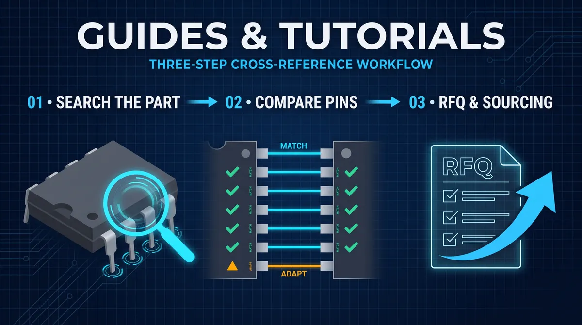
An operational amplifier replacement is a substitution that an enormous share of electronics work touches, because the op-amp is the most widely used building block in analog design, and every op-amp eventually faces obsolescence, shortage, a price change, or a need for a second source. The operational amplifier, commonly called the op-amp, is an integrated circuit that amplifies the difference between two input signals with very high gain, and its versatility, as an amplifier, a buffer, a filter, a comparator, an integrator, and a level shifter, makes it the component that hundreds of thousands of designs share. When a design's op-amp goes unavailable, the buyer and the engineer face a familiar choice: find an op-amp equivalent that can replace it on the same board, or rework the board around a new part. This guide gives the full operational amplifier replacement method, the parameters that decide compatibility, the configuration and package matching, the speed and precision trade-offs, and the special cases like audio and precision, so that an op-amp substitution is a documented engineering decision rather than a bench experiment.
The reason op-amp replacement deserves its own guide is that the op-amp's compatibility is decided by parameters that a pin count does not reveal. Two op-amps in the same SOIC-8 package with the same pinout can differ in supply range, input offset, bandwidth, slew rate, output swing, and noise, and a substitution that matches the pins but not the parameters will work on the bench and fail in the product. The good news is that the op-amp world is full of compatible families: the LM358 dual and the LM324 quad pinouts are shared across a wide field of manufacturers, the TL072 and the NE5532 have long replacement histories in the audio world, and the 741 legacy pinout remains the reference for a whole class of general-purpose parts. The guide walks the comparison that makes these replacements safe, because the parameter that separates a true drop-in from a quiet failure is always found in the datasheet, never in the part number.
What an Operational Amplifier Replacement Must Match
An operational amplifier replacement is compatible when it matches the original across four dimensions: the configuration, the package and pinout, the electrical parameters, and the behavior in the circuit. The configuration is the number of amplifiers in the package, single, dual, or quad, because a dual op-amp is not a replacement for a single, and the circuit that uses both halves of a dual cannot be served by two singles without a board change. The package and pinout decide whether the replacement physically fits: the same package code and the same pin functions, so the part mounts on the existing footprint and the schematic does not change. The electrical parameters decide whether it works: the supply voltage range, the input voltage range and the offset and bias currents, the output swing and drive, the bandwidth and slew rate, the noise, and the operating temperature grade, matched to the circuit's requirements. The behavior in the circuit is the final referee: the replacement is tested in the actual application across the operating range and temperature, because the parameters interact in ways the datasheet lines do not predict. A replacement that matches all four is a drop-in; a replacement that matches three is a candidate that needs a documented adaptation; and a replacement that matches fewer is a redesign in disguise.
The compatibility method is the same for every op-amp because the four dimensions are universal, but the weight of each dimension changes with the application. A power or motor-control application weighs the output swing and the supply range heavily, because the amplifier has to reach the rails and drive the load. A sensor or instrumentation application weighs the input offset, the bias current, and the noise, because the smallest signal errors dominate. An audio application weighs the bandwidth, the slew rate, the noise, and the distortion, because the human ear is the final test. A filter application weighs the bandwidth and the open-loop gain at the operating frequency, because the filter's shape depends on the amplifier's behavior. The guide treats all the dimensions and then calls out the applications, because a safe operational amplifier replacement is not the one that matches the most dimensions in absolute terms, it is the one that matches the dimensions the design actually depends on.
The configuration trap in op-amp replacement
The configuration is the first trap in op-amp replacement, because the package can hide the count. A single op-amp in an SOIC-8 and a dual op-amp in an SOIC-8 share a package and even a pin count, but the pin functions are different: the single uses pins 2, 3, 6 for its input and output while the dual divides the package between two amplifiers, and substituting a single for a dual leaves half the circuit unconnected and the other half mis-wired. The quad is worse, because the 14-pin quad layout packs four amplifiers and the pinout is a specific alternation that no single or dual mimics. The first check in any op-amp replacement is therefore to confirm the configuration matches, and the second is to confirm the exact pinout, not just the package, because even within the dual family the second-amplifier pin order varies between some historical parts. A replacement that clears the configuration check is ready for the electrical comparison, and one that does not is finished before it starts, which is why the configuration is listed first in every serious substitution procedure.
How to Compare the Supply, Input, and Output of an Op-Amp
The supply comparison is the electrical foundation of an op-amp replacement, and it starts with the operating supply range and the maximum rating. An op-amp runs on a single supply, a positive rail and ground, or a split supply, a positive and a negative rail, and the replacement must accept the supply the design provides, not merely a supply it can tolerate. Compare the supply voltage range, the absolute maximum rating, and the quiescent current, because a replacement with a higher quiescent current changes the board's power budget and its heat, and one with a lower range cannot run on the rail the design uses. The input comparison follows, and it matters because modern op-amps are often specified with rail-to-rail inputs that older parts lack: compare the common-mode input voltage range, whether it reaches the rails, and the input offset voltage and bias current, because an instrumentation or sensor circuit reads the offset and bias directly in its error budget. The output comparison closes the group, comparing the output swing, whether it reaches the rails, the output current drive, and the load the amplifier drives, because a design that needs the output to reach the rail will see a part that cannot reach it as a clipping failure. The supply, input, and output comparison is the group that decides whether the replacement works at the circuit's operating points, and it is the group that most replacements pass or fail in.
The comparison also catches the parts that look identical and behave differently. Two dual op-amps with the same package, the same pinout, and the same supply range can still differ in input stage, one bipolar and one CMOS or FET-input, and the difference shows as different bias current, input noise, and input voltage range, which can be invisible to a quick check and fatal to a precision design. A bipolar-input replacement of a FET-input original adds bias current to a high-impedance source and shifts the output; a CMOS-input replacement of a bipolar original can exceed the input range tolerance on a low-impedance source. The datasheet's input specification is therefore read for the actual circuit, the source impedance, the signal range, and the error budget, and the replacement is chosen to match the input behavior the design needs rather than the family name the designer remembers. The supply, input, and output review done carefully is the difference between a replacement that passes on the bench and one that passes in the field.
How to match the output swing and drive of an op-amp
The output behavior of an op-amp is specified as the swing toward the rails under a load, and matching it is decisive for the applications that drive the output hard. Compare the output voltage swing at the design's load current and supply, because a part that swings to within a few hundred millivolts of the rail is different from one that stops a volt short, and a circuit that expects the former sees the latter clip. Compare the output current capability, because a design that drives a low-impedance load needs an amplifier rated for that current, and a general-purpose part that cannot deliver it sags under load. Compare the output behavior into capacitive loads, because the stability of an op-amp with a capacitor on the output depends on the internal compensation, and a replacement with different compensation can oscillate where the original was stable. For the applications that need the output to swing the full range, the rail-to-rail output specification is the field to check, and for the applications that drive a heavy or reactive load, the short-circuit and thermal protection behavior matter too. The output review is the group that protects the load, and it is the reason an operational amplifier replacement is chosen with the circuit's output stage in mind rather than with the amplifier's family name alone.
How to Match Speed and Bandwidth in an Op-Amp Replacement
The speed and bandwidth comparison is where an op-amp replacement succeeds or fails silently, because a part that matches every static parameter can still be too slow, too fast, or too noisy for the signal it must process. The three speed parameters that matter are the gain-bandwidth product, which states the frequency at which the open-loop gain falls to unity and sets the usable bandwidth for a given gain, the slew rate, which states how fast the output can change and decides the large-signal bandwidth and the ability to reproduce a fast step or a high-amplitude high-frequency signal, and the settling time, which matters in sample-and-hold and data-conversion circuits. Compare these against the signal the circuit carries, and against the original part, because a filter designed around one bandwidth responds differently with a replacement whose bandwidth is higher or lower. A replacement with a much higher bandwidth can actually be worse, because it passes more noise and can make the circuit oscillate where the original's lower bandwidth was stable, which is the classic reason a general-purpose part is sometimes the right choice over a faster one.
The speed comparison also has to account for the interaction between gain and bandwidth. The gain-bandwidth product is a constant for a voltage-feedback op-amp, so the achievable bandwidth drops as the gain rises, and a replacement must be checked at the gain the circuit actually uses rather than at unity gain. The slew rate sets the limit for high-amplitude signals, so a design that drives a fast, large-amplitude signal needs a replacement with the slew rate to reproduce it, and the datasheet's slew rate is read at the operating supply and load. For the precision and audio circuits, the speed comparison extends to the settling time and the distortion at frequency, and for the high-speed circuits it extends to the phase margin and the stability with the board's parasitic capacitance. The speed review is the group that protects the signal, and it is the reason an operational amplifier replacement is tested in the circuit at the signal it actually carries, not at the datasheet's ideal conditions.
How to compare bandwidth and slew rate when replacing an op-amp
The comparison of bandwidth and slew rate is a matter of placing the original and the replacement side by side on the same parameters, then judging the difference against the circuit. Pull the gain-bandwidth product from both datasheets and compare them at the gain the circuit uses, remembering that the achievable bandwidth scales as gain-bandwidth divided by gain. Pull the slew rate from both and compare them against the signal's maximum rate of change, using the rule that the slew rate must exceed the signal amplitude multiplied by the angular frequency for the signal to be reproduced without slew limiting. Check the settling time for the circuits that need a precise final value, the data-conversion and sample-and-hold designs, and check the phase margin and the compensation for the circuits that run near the amplifier's limits. When the comparison is close, the tiebreaker is the actual circuit: a sample of the replacement is mounted and the design's own signal is applied, and the measured bandwidth, the rise time, and the stability are compared to the original's. A replacement that matches on the datasheet and confirms on the bench is the replacement that can go to production, and one that differs anywhere is returned to the candidate list rather than risked on the line.
How to Find Op-Amp Equivalent Parts
Finding op-amp equivalent parts is the search that feeds the replacement, and it runs through the same channels that any component search uses, with the op-amp's parameters as the filter. The first channel is the cross-reference database, a distributor's alternative-part feature, an aggregation platform, or a dedicated cross-reference engine, where the original part number returns a candidate list, and the list is then filtered by the parameters that matter to the design, the configuration, the package, the supply range, and the bandwidth. The second channel is the manufacturer's own selection tools and alternate-part tables, which list the vendor's recommended replacements and the differences between them, and which are the most authoritative source for a part from that vendor. The third channel is the engineering community, the forums and the application notes where designers document which parts they used to replace which, and which is valuable as a pointer to the candidates the databases may miss. The search habit is the same one that protects every substitution, collect from more than one source, sort by trust tier, and verify every candidate against the datasheet before the engineering review begins.
The search also benefits from knowing the op-amp families that are genuinely interchangeable. The LM358 and the LM324 pinouts are shared across a wide field of manufacturers, and a replacement within the dual or quad family is a candidate before the electrical review even starts. The TL072 and the NE5532 have long replacement histories in the audio world, and the precision and low-noise families have documented alternates in the catalogs of the major vendors. The legacy 741 pinout is the reference for a whole class of general-purpose parts, and many vendors produce pin-compatible descendants. For the microcontroller-era designs, the comparator family, LM393 and its kin, follows the same pinout pattern and the same search method. The family knowledge turns the search from a blind query into a short list, and the datasheet review turns the short list into a decision, which is the entire shape of finding an op-amp equivalent that the engineering team can trust.
When to cross-reference an op-amp by its function
Cross-referencing an op-amp by function rather than by number is the fallback when the original number is obscure, obsolete, or unmarked, and it works because the op-amp's role determines its requirements. Describe the function, a dual general-purpose amplifier, a low-noise audio amplifier, a quad comparator, a precision instrumentation amplifier, a high-speed buffer, and state the package and the key parameters, the supply range, the bandwidth, the slew rate, the input type, and the output swing, and the search tools return the candidates that meet the description. The function-based search is slower than a number search but it reaches parts the number search cannot, because the obscure original may have dozens of functionally equivalent alternatives that no database has mapped under its specific number. The function search also carries the verification burden in full, because a functional match without the exact pinout is a redesign waiting to happen, so the candidates are checked for the configuration, the package, and the pinout before the electrical review. For the unmarked or discontinued part, the function search is often the only path, and the datasheet review plus the bench test are the entire proof that the replacement is right.
Special Cases: Audio, Precision, Low-Power, and High-Speed Op-Amps
The op-amp replacement guide would be incomplete without the applications where the standard comparison changes weight, and four special cases cover most of them. The audio case weights the noise, the distortion, the bandwidth, and the slew rate heavily, because the listener is the final instrument, and the replacement is chosen and auditioned on the actual signal path, with the TL072 and NE5532 families as the historical benchmarks. The precision case weights the input offset voltage, the offset drift over temperature, the bias current, and the CMRR, because the circuit's accuracy is the product, and the replacement is chosen against the error budget rather than the headline speed. The low-power case weights the quiescent current and the supply range, because the battery life is the product, and a replacement that doubles the quiescent current can halve the run time even when every other parameter matches. The high-speed case weights the bandwidth, the slew rate, the settling time, and the stability, because the signal integrity is the product, and the replacement is tested on the board with the actual parasitics. Each special case follows the same four-dimension method but with its own dominant dimension, which is the point of calling them out.
The special cases also carry the discipline that keeps a general guide safe in a specific design. The audio replacement is not an excuse to ignore the supply and the output, because a rail-to-rail supply swing still has to be in the data. The precision replacement is not an excuse to ignore the speed, because a low-offset part that is too slow still cannot serve a fast signal. The low-power replacement is not an excuse to ignore the drive, because the battery still has to drive the load. The high-speed replacement is not an excuse to ignore the offset, because a fast part with a large offset still corrupts a precision input. The method holds its four dimensions in every case, and the special case only changes which dimension is checked first and heaviest. That is the difference between a guide that covers the subject and a method that covers the part, and the method is what the buyer and the engineer take into the design.
When to Replace an Op-Amp and When to Redesign Around It
The replacement decision for an op-amp has the same three options as any component, source the original, substitute an equivalent, or redesign the board, and the op-amp's role decides which. A general-purpose op-amp in a standard configuration is the easiest substitution in electronics, because the families are interchangeable and the qualification is a datasheet review and a bench test, so a substitute is usually the answer. A precision, audio, or safety-critical op-amp is a heavier decision, because the parameters and the certification matter more, and the substitute has to match the full application rather than the headline data. A proprietary or certified op-amp, an application-specific amplifier or a part under an agency approval, is the redesign case, because no substitute carries the same approval and the qualification would exceed the redesign's cost. The decision is recorded with the evidence, the original part, the reason for the change, the candidate list, the verification results, and the choice, so the next reviewer and the next audit see the reasoning. The op-amp replacement is the perfect example of a substitution where the board often does not change at all, and where the discipline of the datasheet review is the entire difference between a safe swap and a field failure.
The redesign case is entered when no source and no substitute can carry the part, and it is the honest answer when the original is certified, the footprint is unique, or the performance is beyond any alternative. The redesign around a current op-amp family updates the schematic, the layout, and the firmware where the amplifier is read by a converter, and it inherits the full qualification cost and timeline. The transition plan keeps the legacy design shipping on stock and substitute while the new design is qualified, and it documents the schedule so the change is deliberate. The decision between replacement and redesign is made on the same evidence in every case, the product's remaining life, the part's availability, and the cost of each path, and the op-amp's replacement history is so rich that the redesign is genuinely the last resort. A team that knows the families, checks the four dimensions, and tests on the bench can substitute an op-amp in a day, and that speed is the reason the operational amplifier remains the friendliest component in the catalog to replace safely.
Worked Example: Choosing an Equivalent for an Audio Op-Amp
Choosing an equivalent for an audio op-amp is the worked example that shows how the four dimensions and the audio special case come together, and a dual op-amp in a line-level audio path is the classic case. The original part determines the candidate's requirements: the five-dimension review reads the supply, the package, the pinout, the bandwidth, and the slew, and the audio path adds the noise, the distortion, and the output drive to the weight. A candidate in the same SOIC-8 with the same dual pinout, a supply that matches, a bandwidth at the audio band, a slew above the signal's rate, and a drive that handles the load, is a candidate on the shortlist, and the datasheet curves are read for the noise and the distortion at the audio frequencies rather than at the headline numbers. The bench test then mounts the candidate in the actual audio path and the listening test, or the measurement of the distortion and the noise at the design's frequencies, decides the final pick. The worked example shows the audio op-amp replacement as the four-dimension method with the audio weight added, and it is the same method the general-purpose replacement uses with different weights.
The worked example also reads the candidate families that the audio world standardizes on, because the audio path has its own shortlist. The TL072 with its JFET input and its clean audio character, the NE5532 with its higher drive and its wider bandwidth, and the LM833 and the other audio-grade parts are the candidates an audio replacement searches, and the general-purpose LM358 and LM324, which share the pinouts, are the parts the audio path usually skips for the reasons the audio section read. The data, the supply, the bandwidth, the noise, and the slew, and the listening or the measurement result, choose between the candidates, and the chosen part is often a pin-compatible swap in the same socket. The worked example shows the audio replacement as a family-aware search, and it is the search the special-case section set up, which is the concrete face of the audio op-amp replacement.
How to Measure the Load, the Slew, and the Distortion on the Bench
Measuring the load, the slew, and the distortion on the bench is the verification that the four dimensions and the special cases predict, and it runs a short sequence that any lab can follow. Measure the output drive and the swing first, driving the design's load and reading the output voltage swing against the supply, and the result confirms the output dimension that the datasheet predicted. Measure the slew rate next, applying a large-signal step and reading the output's slope on the scope, and compare the measured volts-per-microsecond against the datasheet, because a candidate whose slew falls short of the design's signal rate slew-limits and distorts. Measure the bandwidth, applying a small signal and sweeping the frequency until the gain drops, and read the gain-bandwidth product, and measure the distortion, where the design's high-fidelity path, with a low-distortion source and an analyzer, reads the THD at the operating level. The three measurements are the bench's answer to the datasheet's claim, and the record, the swings, the slew, the bandwidth, and the distortion, is the evidence the substitution file carries.
The measurements also read the margins that the datasheet's typical values hide, because the bench at the design's operating point and the datasheet at the ideal point differ. A candidate whose slew measures at the datasheet's minimum rather than its typical, or whose distortion rises at the design's frequency though the datasheet prints a low number, is a candidate the bench corrects, and the correction is the reason the substitution always ends at the board. The measurement procedure is the same for the general-purpose, the audio, and the precision candidates, with the weights the application sets, and it is the procedure that completes the four-dimension method. The bench is the referee of the op-amp replacement, and the measurements are its verdict, which is the practical completion of the worked example.
Op-Amp Failure Symptoms That Point to the Wrong Part
The op-amp failure symptoms that point to the wrong part are the diagnostic half of the guide, and reading them prevents a field failure from becoming a mystery. A rail-to-rail signal that clips is the symptom of an output-swing mismatch, the candidate cannot reach the rail the original did, and the fix is the output-dimension check and the right part. A slow, slewed, or distorted signal is the symptom of a speed mismatch, the bandwidth or the slew falls short of the signal's rate, and the fix is the gain-bandwidth and the slew read. An output that drifts or carries the offset is the symptom of an input mismatch, the offset or the bias differs from the design's error budget, and the fix is the precision read and the balance. A circuit that oscillates or does not settle is the symptom of a stability or a compensation difference, and a filter that rings or a buffer that oscillates is the symptom of the bandwidth or the phase mismatch, and the fix is the speed read and the stability test. Each symptom maps to a dimension, and the mapping is the diagnosis that the four-dimension method provides.
The symptoms also read the application that the wrong part entered, because the same symptom points differently by the circuit. A clipping audio signal and a clipping control signal both read the output swing, but the audio one also reads the drive and the load, and a drifting sensor output and a drifting level-shifter output both read the offset and the bias, but the sensor one reads the error budget harder. The diagnosis therefore runs the application's weights, which is the same weighting the selection used, and the fix selects the part whose dimensions match the application's needs rather than the part that fixes the single symptom in isolation. The failure symptoms are the field bookend to the selection method, and they are the practical reason the four dimensions are read before the part rather than after the failure, which is the close of the diagnostic half of the op-amp replacement guide. The breadboard step, where the candidate is first mounted in the actual stage rather than on a generic test fixture, is the simplest version of the same diagnosis, because the layout, the supply, and the load of the real stage surface the symptoms that a bare fixture hides, and a candidate that behaves on the bench fixture and misbehaves in the stage is caught at the breadboard before it reaches the production board. The same diagnosis applies in reverse to the parts that were already shipping, because an op-amp that was fine and then drifts or clips often signals a change in the supply, the load, or the temperature rather than a failure of the part itself, and the symptom read separates the part problem from the system problem before a needless replacement is ordered.
A Workflow for a Safe Operational Amplifier Replacement
The full method compresses into a workflow that an engineer or buyer runs in the same order, and it is the operating shape of this guide. First, capture the original part, its number, its package, its configuration, and its role in the circuit, and pull its datasheet, the archived copy if the manufacturer has removed it. Second, search for the candidates, through the cross-reference databases and the manufacturer tables, and collect more than one list. Third, compare the four dimensions, the configuration and package and pinout, the supply, input, and output, the speed and bandwidth, and the special-case parameters for audio, precision, low-power, or high-speed designs, and rank the candidates by the match. Fourth, select the best candidate and verify it on the bench, mount the sample in the actual circuit, apply the design's own signals across the operating range and temperature, and compare the measurements to the original part. Fifth, record the decision, the candidate, the comparisons, the test results, and the change note, and update the BOM and the cross-reference library. Sixth, watch the replacement, re-checking it at the next review for drift and for the availability of the next part in the family. That sequence is the operational amplifier replacement method, and it is the same method whether the part is an LM358, a TL072, a NE5532, or the newest precision part.
The workflow is the reason the phrase operational amplifier replacement names one of the friendliest substitutions in electronics. The op-amp is standardized, the families are interchangeable, the datasheets are complete, and the test is a bench, so a replacement can be qualified in hours rather than months. The value of the method is that the speed is earned honestly, with the four dimensions compared, the special cases weighed, and the bench test run, so the speed does not come at the cost of the safety. A buyer and an engineer who run this workflow substitute an op-amp with a documented, tested, qualified part, and the board they never changed keeps shipping exactly the way it did, which is the entire point of an operational amplifier replacement done right.
Not sure which sensor fits your project?
Talk to our mmWave application engineers for a free consultation.
Specify your hotel project with our engineers
Send your room count, ceiling type, and protocol preference. We will return a sample plan and quote within 24 business hours.
- Move from general guidance into a product or application discussion.
- Use RFQ when pricing, drawings, MOQ, or launch timing needs structure.
- Keep a direct contact path visible for fast clarifications and handoff.