Logic IC Equivalent: A 74-Series Replacement Guide
Logic IC equivalent guide: how to cross-reference 74-series logic parts by function number and match family, voltage, and speed for a safe substitute.
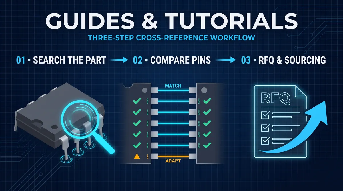
A logic IC equivalent is an integrated circuit that performs the same logic function, in the same package and pinout, as another logic chip, so it can substitute for the original on the same board, and the logic world is built around a numbering system that makes these equivalents easier to find than in almost any other component category. The 74-series numbering system defines the function of every part by its base number: a 7404 is a hex inverter, a 7408 is a quad two-input AND gate, a 74595 is an 8-bit shift register, a 74245 is an octal bus transceiver, and the function number is shared across manufacturers and across logic families. That means a logic IC equivalent is found by matching the function number and then matching the family, the package, and the voltage and speed grade, and the substitution preserves the board because the pinout follows the function number. This guide explains the 74-series organization, the logic families and their voltage and speed differences, the special types like open-collector, Schmitt, and tri-state outputs, and the workflow that makes a logic IC substitution safe, so that the most interchangeable parts in electronics are replaced with the confidence the catalog promises.
The logic IC equivalent question is the friendliest substitution in electronics because the numbering system does most of the work, and the traps are the details around the function number. Two parts with the same function number in the same package are usually pin-compatible, but the family suffix decides whether they run on the board's supply and levels: a 74HC595 and a 74HCT595 share the function and the pins, yet the input thresholds differ, and a 74LS04 and a 74HC04 share the hex inverter function yet the input levels and output drive differ. The engineer who knows the family system reads a part number like 74HC595D and sees the function, the family, and the package in one glance, and that reading is the core skill of logic replacement. This guide builds that reading from the ground up, because a logic IC equivalent is only an equivalent when the family, the voltage, and the speed serve the surrounding circuit, and the guide's method checks each one before the part goes near the board.
What a Logic IC Equivalent Is and Why the Number System Makes It Easy
A logic IC equivalent is a part that carries out the same digital logic function with the same input and output behavior as the original, in a package and pinout the board already fits, and the 74-series numbering system is what makes equivalents systematic. The base number names the function, the family prefix and suffix name the technology and the package, and the combination is standardized across the industry, so a design that uses a 7400-family part can be served by any manufacturer that produces the same function number. The pinout follows the function number: a hex inverter is a 14-pin part with six inverters on the same pins regardless of who made it, a quad two-input gate is the same eight gates in the same positions, and a shift register or counter places its data, clock, and output pins on the same positions across vendors. The consequence is that the first step of finding a logic IC equivalent is reading the function number, and the second step is confirming the family and package, and the rest of the substitution is a datasheet review that is short because the numbering system already did the mapping.
The same logic applies to the 4000-series CMOS parts, the CD4017 decade counter and the CD4060 oscillator-counter that still populate boards, which carry their own function-number system and their own pinout conventions. The 74 and the 4000 series are different worlds, a 4000-series part does not substitute for a 74-series part by number, and the guide treats them separately because the substitution rules differ. Within the 74 series, the function number is the reliable anchor, and within the 4000 series the same. The buyer or engineer who memorizes the handful of functions their boards use, the inverters, the gates, the registers, the counters, the buffers, and the transceivers, can cross-reference a logic part in seconds, because the number names the function and the function names the pins. That speed is the entire reason the logic IC equivalent question has a guide, the answer is systematic, and the systematic answer is the most dependable one in electronics.
How the 74-series function number maps to a logic IC equivalent
The function number is the map that makes logic replacement fast, and reading it is a three-part skill. The first part is the family prefix, the letters before the number that name the technology, 74 for the TTL-originated series, and the family suffix after it, LS for low-power Schottky, HC for high-speed CMOS, HCT for CMOS with TTL input levels, AC, AHC, LVC, and the rest, and the prefix and suffix together state the voltage and speed world the part lives in. The second part is the base number itself, which names the function, and the third is the package suffix, the letter and digits that state the package type, D for SOIC, N for DIP, PW for TSSOP, and the like. When the board needs a replacement, the function number is held fixed and the family and package are matched against the circuit, so the search returns the candidates that share the function and the pins, and the datasheet review filters the family differences. The number system is the reason a cross-reference tool returns a usable short list for logic parts, and it is the reason the engineer can trust the list before the datasheet review, because the function number already guaranteed the pinout.
Logic Families, Voltage Levels, and the Substitution Trap
The logic family is the technology inside the part, and it decides the voltage and speed behavior that the function number does not, so matching the family is where a logic IC equivalent is won or lost. The original 74 family is bipolar TTL running on a 5-volt supply, the LS family is low-power Schottky TTL on the same 5 volts with lower current, and the CMOS families, HC, HCT, AC, AHC, and LVC, run on supply ranges from a few volts to several, with HC and AC running on 2 to 6 volts and LVC running down to 1.2 volts for the low-voltage world. The substitution trap is that two parts with the same function number can belong to different families and therefore to different voltage worlds: a 74LS04 runs on 5 volts with TTL input thresholds, a 74HC04 runs on 2 to 6 volts with CMOS thresholds, and a 74LVC04 runs on the low-voltage supplies, so swapping one for another changes the input levels the circuit sees and the output levels the circuit drives. The family match is therefore checked against the board's supply rail and the receiving circuit's input requirements, not against the manufacturer's catalog alone.
The family comparison runs on the two specifications that decide behavior: the input threshold and the output drive. The input thresholds matter because a CMOS input requires its signal to reach the CMOS thresholds, roughly 0.7 of the supply for a high and 0.3 for a low, while a TTL input accepts a high above about 2.0 volts on a 5-volt rail, so a part with the wrong family can see a valid TTL signal as invalid, or accept a signal a CMOS part would reject. The output drive matters because a CMOS output delivers more current than an LS output, and a circuit built around an LS part's drive sees different edge times and different loading from an HC part. The matching habit is to read the board's supply rail, the driver's output levels, and the receiver's input thresholds, and to choose the family whose levels and drive fit, rather than to assume that the same function number is the same part. A logic IC equivalent that matches the family is a drop-in; one that matches the function but not the family is a candidate for a level-adapter or a redesign.
How to match the logic family to the board supply
The board supply decides the family, and the matching is a simple rule with a few common cases. A board running on a 5-volt rail and built with TTL or LS logic is served by an LS, HC, or HCT replacement whose supply range includes 5 volts, with the input-level difference handled by choosing HCT, which accepts TTL levels at 5 volts, when the driving circuit is TTL. A board running on a 3.3-volt rail is served by the HC, AHC, or LVC families whose supply range includes 3.3 volts, and a mixed 5-volt-and-3.3-volt board checks the interface parts, the level shifters and the transceivers, separately. A board running on a low-voltage rail below 3 volts is served by the LVC and AHC families designed for it. The substitution rule is to confirm the replacement's supply range includes the board's rail, confirm the replacement's input thresholds accept the driving levels, and confirm the output levels drive the receiving circuit, and then the family is matched. The rule is the same for the 4000-series CMOS parts, which run on a wide supply range and are matched by supply and by the function number, and it keeps a logic IC equivalent from becoming a voltage mismatch on the bench.
Speed and Timing: Propagation Delay in a Logic IC Equivalent
The speed of a logic part is stated by its propagation delay, the time a signal takes from an input edge to the corresponding output edge, and it is the parameter that makes a logic IC equivalent fail silently. A replacement with the same function, family, and package can still be too slow for the circuit, delaying the signal past the receiving device's setup time and corrupting the data, or too fast, delivering an edge that races through a circuit tuned to the original's delay. The family comparison covers much of the speed question, because the families differ in speed, an AC or AHC part is faster than an HC part, which is faster than an LS part at the same supply, and the datasheet's propagation delay values state the actual numbers. The engineer compares the replacement's propagation delay at the operating supply and load against the original's and against the timing budget of the receiving circuit, and the comparison runs for every path that matters, the clock path, the data path, the enable path, and the control path. A replacement that meets the timing budget on paper is then confirmed on the bench, where the measured delay and the circuit's behavior are compared to the original.
The timing review also covers the parameters the datasheet lists around the propagation delay, the setup and hold times of the registers and the flip-flops, the minimum pulse widths, and the maximum clock frequency, and it checks them against the signal the design actually sends. A shift register that accepts the original's clock rate may miss the next faster clock on a slower replacement, and a counter that the design clocked at its maximum may need headroom on the replacement. The engineering habit is to keep the timing margin rather than to run at the datasheet limit, because the board's parasitic capacitance and the temperature range reduce the real margins, and a replacement that passes at 25 degrees can miss at the product's ambient range. The speed review is the layer that protects the logic's timing, and it is the reason a logic IC equivalent is chosen with the circuit's clock and the receiving devices in view, not with the function number alone.
How to compare propagation delay when substituting logic
Comparing propagation delay is a matter of pulling the value from the datasheet at the operating conditions and judging the difference against the circuit. Read the propagation delay from both datasheets at the same supply voltage, the same load capacitance, and the same temperature grade, because the delay scales with all three, and compare the worst-case values rather than the typical ones, since the worst case is what the circuit must tolerate. Add the setup and hold time of the receiving device to the comparison, because the total budget is the driver's delay plus the receiver's requirement, and check the maximum clock frequency where the design runs a clocked device. When the comparison is close, mount a sample and measure the actual delay with an oscilloscope at the operating conditions, and confirm the circuit's behavior across the temperature range the product sees. The measured comparison is the referee that the datasheet numbers cannot fully provide, and a replacement that matches on the datasheet and confirms on the bench is the replacement that can go to production, while one that differs anywhere is returned to the candidate list.
Special Logic Types: Open-Collector, Schmitt, Tri-State, and Buffered Outputs
Beyond the family and the speed, the logic types with a special output or input behavior deserve their own check, because the function number does not always state the type. The open-collector and open-drain parts, the 7407 and the 74LS06 and their kin, pull their output low through the collector and rely on an external pull-up resistor for the high level, and a replacement without the open-collector output cannot drive the wired-OR bus or the load that the design assumed, so the open-collector type is matched explicitly. The Schmitt-trigger parts, the 7414 hex inverter with Schmitt inputs, accept slow or noisy input edges and produce clean outputs, and a replacement without the Schmitt input misses the noise immunity the design needs, so a 74HC14 is not a substitute for a 74HC04 when the input is a slow analog edge. The tri-state parts, the 74244 and the 74245 buffers and transceivers, add the output-enable control that lets multiple drivers share a bus, and a replacement whose enable behavior or polarity differs breaks the bus arbitration. The buffered and unbuffered distinction, most visible in the 4000 series where a CD4017 is buffered and some CD4000 parts have unbuffered variants, changes the drive and the timing, and it is checked from the part number and the datasheet.
The special-type check is a reading of the datasheet's features and pin functions, and it follows the part's role in the circuit. A logic equivalent that drives a bus checks the tri-state and the enable behavior. A part that receives a slow or noisy signal checks the Schmitt inputs. A part that drives a wired-OR or an indicator checks the open-collector or open-drain output and the pull-up requirement. A part that drives a heavy load checks the output drive and the family's current rating. Each check is a single datasheet line, and together they cover the behaviors the function number does not state, which is exactly the layer where a logic IC equivalent surprises a designer. The guide's method reads the type, the family, the speed, and the voltage before the part is trusted, and the special-type read is the difference between a substitution that works on paper and one that works in the field.
Why a Schmitt trigger logic part is not always an equivalent
The Schmitt trigger deserves its own caution because its function number can look identical to the non-Schmitt version. A 74HC14 and a 74HC04 are both hex inverters in the same package and pinout, and the 74HC14 is often listed as a drop-in equivalent for the 74HC04 in a cross-reference table, but the two differ in a behavior the function number hides: the 74HC14 has Schmitt inputs with hysteresis, and the 74HC04 does not. In a circuit where the input is a clean digital edge, the difference is invisible, and in a circuit where the input is slow, noisy, or a slowly rising RC edge, the Schmitt part cleans the output while the non-Schmitt part can oscillate or produce multiple edges. The substitution therefore reads the design's input condition, not just the function number, and when the original was a Schmitt part, the replacement must be a Schmitt part, and when the original was not, a Schmitt replacement is usually fine but still checked for the drive and speed. The caution is the model for every special type, the function number names the function, and the type names the behavior, and a logic IC equivalent must match both.
How to Find Logic IC Equivalents by Cross-Reference
Finding a logic IC equivalent runs through the same cross-reference channels as any component, with the function number as the search key. The first channel is the cross-reference tool, a distributor's alternative-part feature, an aggregation platform, or a dedicated cross-reference engine, where the original part number returns the candidates that share the function and the pins, and the family and package filters narrow the list. The second channel is the manufacturer's own catalog and cross-reference, where a vendor lists its family lineup, the HC, HCT, AC, and LVC versions of the same function, with the speed and voltage differences stated, and this channel is the most authoritative for a part from that vendor. The third channel is the logic-family cross-reference tables that the industry has maintained for decades, the lists that map a 74HC function to its LS, AC, and CD4000 counterparts, and these tables are the legacy of the numbering system that makes logic substitution systematic. The search habit is the same as for any part, collect from more than one source, sort by trust tier, and verify the candidates against the datasheet before the review.
The search also has a practical shortcut that the logic world rewards: search by the function number alone. Because the function number names the function and the pins, a search for 74595 returns the shift register family, a search for 74245 returns the transceiver family, and the candidates that share the number are pin-compatible by construction, which is the reason a logic cross-reference returns fewer false positives than any other category. The remaining filters are then the family, the supply, the speed, and the package, and the datasheet review confirms the levels, the drive, and the timing. For the 4000-series parts, the same search by function number works, with the supply range and the buffered or unbuffered type as the filters. The search by function number is the fast path, and the datasheet review is the safe path, and the two together are the logic IC equivalent method in its full shape.
How to cross-reference a 74-series part by its function number
Cross-referencing by function number is a three-line habit. First, read the base number from the part, 74595, 74245, 74138, and treat it as the function's name. Second, search that number in the cross-reference tool and the manufacturer catalog, and collect the family versions, the HC, HCT, LS, AC, and LVC parts with the same function, and the package versions of each. Third, filter by the board, the supply rail picks the family, the timing budget picks the speed, and the footprint picks the package, and then verify the chosen candidate against the datasheet, the input thresholds, the output drive, the propagation delay, and the special type. The habit is fast because the number does the mapping, and it is safe because the datasheet does the checking, and a buyer or engineer who runs it can replace a logic part in minutes. The function-number cross-reference is the reason the logic IC equivalent question has the friendliest answer in component substitution, and it is the habit this guide exists to give every team.
When a Logic Equivalent Is Not a Drop-In
The honest limits of logic substitution are the cases where the function number alone cannot save the design, and knowing them keeps a logic IC equivalent from becoming a redesign in disguise. The first limit is the special-type mismatch, the open-collector, Schmitt, tri-state, and buffered or unbuffered differences that the function number does not state, which force a careful datasheet read and often rule out a candidate. The second limit is the voltage world, a board running a 5-volt TTL input driving a CMOS part, or a low-voltage rail without a level shifter, where the equivalent needs an interface part or a redesign rather than a simple swap. The third limit is the certified or safety-critical part, a logic part under an agency approval or a functional safety classification, where the equivalent must carry the same certification and the change must pass the same approval. The fourth limit is the genuinely unique device, a custom logic array or a part with a vendor-specific function that no catalog number matches, where no equivalent exists by definition. Each limit is read before the substitution rather than discovered after, and the reading is the same datasheet review the method always runs.
The response to the limits is the response to every substitution: source, substitute, or redesign. Source the original when the part is still available, substitute the verified equivalent when the board and the circuit accept it, and redesign when the part is certified, unique, or unmatched by any candidate. The decision is recorded with the evidence, the original part, the reason for the change, the candidate list, the datasheet comparisons, and the choice, so the next review and the next audit see the reasoning. A logic IC equivalent program that knows its limits is a program that substitutes the parts that can be substituted and plans the parts that cannot, and that is the difference between a supplier of logic parts and a partner in the supply chain. The limits are not a weakness in the numbering system, they are the boundary of its power, and the professional reader respects the boundary by checking the type, the voltage, the speed, and the approval before trusting the function number.
Worked Example: Substituting a 74HC595 in a Running Design
Substituting a 74HC595 in a running design is the worked example that shows the logic method on the friendliest part, and it is the case the market handles every week. The board uses a 74HC595 in an SOIC-16 driving an LED bank, and the supply issue or the price drives the search for an equivalent. The search by the function number first, 74595, returns the family, and the filter by the family and the package, the HC family, the SOIC-16, and the drive the design needs, narrows the list, and the candidates are the vendor's 74HC595s and the 74HCT595 where the input levels suit the driver. The three-layer review then compares the package, the pinout, and the electrical behavior, the supply range, the input thresholds, the output drive, and the propagation delay, and the bench test mounts the candidate and runs the LED pattern, the clock, the latch, and the temperature. The verified candidate earns its place in the BOM and the cross-reference library, and the worked example is the whole logic method on the friendliest part, which is the model the family-specific sections have set up.
The worked example also reads the family grades that the substitution moves between, because a 74HC595 to a 74HCT595 is a real substitution with a two-line check. The input threshold is the deciding number, the HC's CMOS threshold against the HCT's TTL-compatible threshold, and the driving logic decides which the receiver needs, a microcontroller that drives a clean CMOS signal runs either, and a TTL driver needs the HCT. The drive and the speed follow the family, and the substitution that changes the family verifies the levels and the drive against the driver and the load, which is the check the family section described. The worked example is the concrete face of the family grades, and it is the face that the sourcing and the second-source view then extend, which is the practical completion of the logic substitution method.
Measuring and Troubleshooting the Logic Substitution
Measuring the logic substitution on the bench is the confirmation that the levels, the timing, and the function hold, and it runs a short sequence. Probe the outputs with the oscilloscope while the design drives them, and confirm the high and the low levels against the receiving devices' thresholds, because a level that is valid for one family and marginal for another is the quiet failure that the probe catches. Measure the propagation delay, comparing the output edge against the input edge, and confirm the design's timing budget holds, because a slower replacement delays the signal past the receiving device's setup time. Exercise the special functions, the open-collector pull-ups, the Schmitt noise immunity, and the tri-state enables, against the design's use, and run the temperature pass, because the levels and the delay shift across the range. The measurements are recorded beside the original's readings, and the record is the evidence the substitution file carries, which is the same discipline the series applies to every digital substitution.
The troubleshooting list for the logic substitution covers the failures that a first swap meets. If the outputs stay at the wrong level, check the family's thresholds against the driver, a CMOS input driven by a marginal TTL signal reads the signal wrongly, and check the pull-ups and the pull-downs that the design relies on. If the timing fails, the data corrupts or the counter miscounts, check the propagation delay against the receiving device's setup and hold, and check the clock's rise time against the part's requirement. If a special function misbehaves, the open-collector output never goes high, the Schmitt input never cleans, or the tri-state never releases, check the wiring of the special pins and the enable. If nothing at all works, check the supply and the ground and the part's orientation. The troubleshooting list is the practical bookend to the substitution, and it is the checklist that keeps a logic swap quiet, which is the completion of the worked example and the family sections of this guide.
Logic Family Reference: A Quick Substitution Table
A quick logic family substitution table is the reference that makes the substitution fast, and it maps the families by the supply and the levels. The 74LS family runs on the 5-volt TTL world with the TTL thresholds and the low power, and it is the legacy of the classic boards. The 74HC family runs on 2 to 6 volts with the CMOS thresholds and the high speed, and it is the modern 5-volt and 3.3-volt workhorse. The 74HCT family runs on the 5-volt TTL world with the TTL-compatible input levels and the CMOS output, and it is the bridge that a TTL driver into a CMOS part needs. The 74AC and the 74AHC families run on the higher-speed CMOS with the wider supply and the faster edges, and the 74LVC family runs on the low-voltage rails down to 1.2 volts. The table maps the family to the supply and the levels, and the substitution reads the row that matches the board's rail and the driver's levels. The table is the quick map the selection starts from, and the datasheet is the confirmation, which is the same division of labor the whole guide uses.
The table also reads the direction of the substitution, because not every family row substitutes into every other. An HC part can serve a board that used an LS part when the supply and the levels and the speed all fit, and an HCT part is the cleaner bridge where the TTL levels must be received, and an LS part cannot drive a CMOS input that expects the rail-level highs. The substitution reads the row against the board, and the table's value is the family-aware filter that the datasheet then confirms. The quick table is the reference the engineer keeps beside the bench, and it is the reference that turns a logic substitution from a search into a two-minute read, which is the practical close of the logic family section.
A Workflow for a Safe Logic IC Substitution
The full logic IC equivalent method fits into a workflow that an engineer or buyer runs in the same order, and it is the operating shape of this guide. First, capture the original part, its full number, the family, the function, the package, and its role in the circuit, and pull its datasheet. Second, search by the function number, through the cross-reference tools and the manufacturer catalog, and collect the candidates that share the function and the pins. Third, filter by the board, the supply rail picks the family, the timing budget picks the speed, the footprint picks the package, and the special type reads the datasheet's features. Fourth, verify the chosen candidate, the input thresholds, the output drive, the propagation delay, the special type, and the certification where it applies, and compare the values to the original and to the circuit. Fifth, bench-test the candidate in the actual circuit, apply the design's own signals and clock across the operating range and temperature, and compare the behavior to the original. Sixth, record the decision, the comparisons, the test results, and the change note, and update the BOM and the cross-reference library. That sequence is the logic IC substitution method, and it is the same method whether the part is a 74HC595, a 74LS04, a CD4017, or the newest low-voltage register.
The workflow is the reason the phrase logic IC equivalent names the friendliest substitution in electronics. The numbering system maps the function, the family system maps the voltage and speed, the package suffix maps the footprint, and the datasheet and the bench test map the behavior, so a substitution can be qualified in an afternoon rather than in a month. The value of the method is that the speed is honest, the function number is checked, the family is matched, the special type is read, and the bench test is run, so the speed does not sacrifice the safety. A team that runs this workflow replaces a logic part with a documented, tested, qualified equivalent, and the board that never changed keeps its timing, its levels, and its function exactly as the design intended, which is the entire point of a logic IC equivalent done right.
Not sure which sensor fits your project?
Talk to our mmWave application engineers for a free consultation.
Specify your hotel project with our engineers
Send your room count, ceiling type, and protocol preference. We will return a sample plan and quote within 24 business hours.
- Move from general guidance into a product or application discussion.
- Use RFQ when pricing, drawings, MOQ, or launch timing needs structure.
- Keep a direct contact path visible for fast clarifications and handoff.