AT24C256 EEPROM Replacement: Cross Reference Guide for I2C Memory IC Substitution
Find the right AT24C256 replacement alternative with our comprehensive cross reference guide. Compare pin-compatible I2C EEPROM ICs for industrial and commercial applications.
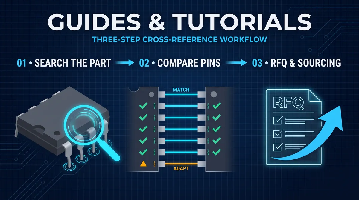
AT24C256 EEPROM Replacement: Cross Reference Guide for I2C Memory IC Substitution
The AT24C256 is a 256-kilobit serial electrically erasable programmable read-only memory (EEPROM) device manufactured by Microchip Technology, featuring a two-wire I2C interface and operating across a voltage range of 1.8V to 5.5V. This widely adopted memory IC serves critical data retention functions in industrial automation systems, consumer electronics, automotive control modules, and telecommunications equipment, where reliable non-volatile storage with over one million erase/write cycle endurance is essential for parameter storage, calibration data, and configuration settings. Engineers and procurement specialists frequently seek an AT24C256 replacement alternative when facing supply chain disruptions, cost optimization requirements, second-source considerations, or specification upgrades. This guide examines pin-compatible substitutes from multiple manufacturers, providing detailed cross-reference data, electrical parameter comparisons, package options, and selection criteria to facilitate informed decision-making for engineering teams and supply chain managers evaluating I2C EEPROM substitution options.
Understanding the AT24C256 Architecture and Specifications
The AT24C256 series represents one of the most deployed serial EEPROM families in embedded systems design, with its architecture optimized for reliability, simplicity, and widespread ecosystem support. Understanding the original device specifications establishes the baseline against which all replacement alternatives must be evaluated, ensuring functional equivalence and compatibility with existing circuit designs and firmware implementations. The device organizes its 256 kilobits (32,768 bytes) of storage as a single contiguous array, accessible through a standardized I2C serial protocol operating at up to 400 kHz in standard mode and 1 MHz in fast mode Plus variants. This memory density strikes an effective balance between capacity and cost, making the AT24C256 suitable for applications ranging from simple configuration storage to complex data logging operations requiring thousands of write cycles over product lifetimes exceeding ten years.
The AT24C256 electrical characteristics include an operating current of 3 mA during active read/write operations, with standby currentdraw of approximately 6 microamps, enabling battery-backed operation in portable and remote installations. The device supports byte-write and page-write operations, with page boundaries aligned at 64-byte segments, allowing efficient firmware storage and retrieval operations when updating configuration parameters or calibration coefficients. The I2C addressing scheme employs a 7-bit device address followed by a read/write direction bit, with the upper four bits fixed at 1010 and the lower three bits configurable through hardware address pins A0, A1, and A2, permitting up to eight AT24C256 devices on a single I2C bus without address collision in multi-memory designs. The write protection pin (WP) provides hardware write prevention when tied high, safeguarding bootloaders and critical firmware sections from accidental modification during field updates or factory programming operations.
Thermal specifications for the AT24C256 span the commercial range (0°C to 70°C), industrial range (-40°C to 85°C), and automotive range (-40°C to 125°C) variants, with the specific temperature grade determined by the product variant suffix. Data retention specifications guarantee a minimum 100-year data retention window at 25°C ambient temperature, with typical endurance ratings exceeding 1,000,000 write cycles per memory cell under specified conditions. These robust specifications have contributed to the AT24C256 becoming a de facto standard in industrial control systems, medical devices, and safety-critical applications where long-term reliability cannot be compromised. The subsequent sections of this guide examine how alternative devices from competing manufacturers deliver equivalent or enhanced performance characteristics, enabling designers to select appropriate substitutes without sacrificing system reliability or requiring extensive hardware modifications.
Why Engineers Seek AT24C256 Replacement Alternatives
Several converging factors drive the ongoing demand for AT24C256 replacement alternatives across the electronics industry, ranging from supply chain volatility and cost pressures to technical obsolescence management and feature enhancement opportunities. The global semiconductor shortage that began in 2020 exposed critical vulnerabilities in single-source component strategies, prompting engineering organizations to establish qualified second sources for mission-critical components including non-volatile memory ICs. The AT24C256, while widely manufactured by Microchip, occasionally experiences allocation challenges during demand surges, particularly for automotive-grade and industrial-grade variants with extended temperature range requirements. Procurement teams facing lead time extensions of 52 weeks or longer have strong incentives to qualify alternative devices that maintain pin compatibility and functional equivalence while offering more reliable availability from multiple qualified suppliers.
Cost optimization represents another significant driver for AT24C256 replacement evaluation, as volume pricing variations between manufacturers can impact product margins substantially when scaling to high-volume production runs. Engineers evaluating BOM cost reduction opportunities often discover that second-source alternatives from ROHM Semiconductor, ON Semiconductor, or other vendors offer pricing advantages of 15% to 30% depending on volume tier and specific variant selection, without requiring any hardware modifications due to pin-compatible footprints. Additionally, some replacement alternatives incorporate enhanced features not present in the original AT24C256, such as extended write cycle endurance ratings, faster I2C clock frequencies, lower operating currents, or expanded voltage range support that can improve overall system performance while maintaining backward compatibility with existing firmware implementations.
The regulatory landscape also influences replacement decisions, particularly for products targeting international markets with varying environmental compliance requirements. The original AT24C256 series has been subject to evolving restrictions under RoHS (Restriction of Hazardous Substances) and REACH (Registration, Evaluation, Authorization, and Restriction of Chemicals) regulations, with some legacy date codes potentially non-compliant with current directives. Alternative devices from manufacturers with updated compliance documentation can simplify market entry processes and reduce compliance verification burden for export products. Furthermore, ongoing technology transitions toward more advanced non-volatile memory technologies, including NOR Flash with SPI interfaces, have created substitution opportunities where system architectures permit interface modifications, though the focus of this guide remains strictly on pin-compatible I2C EEPROM devices that require no hardware changes for direct substitution.
Major Manufacturers Producing AT24C256-Compatible Devices
The market for 256-kilobit I2C EEPROM devices has expanded significantly beyond the original Atmel (now Microchip) AT24C256, with multiple established semiconductor manufacturers offering pin-compatible alternatives that span various quality grades, temperature ranges, and pricing tiers. Understanding the product portfolios and manufacturing capabilities of these alternative suppliers enables procurement specialists and design engineers to construct robust multi-sourcing strategies while maintaining design integrity and supply chain resilience. The primary alternative manufacturers include ROHM Semiconductor with their BR24G256 series, ON Semiconductor with the CAT24C256 family, STMicroelectronics through their M24C256 devices, NXP Semiconductors offering the PCF8582C2 variant, and Samsung Semiconductor with their K24C256 product line. Each manufacturer brings distinct manufacturing processes, quality systems, and regional distribution networks that may influence selection based on specific project requirements and geographic considerations.
ROHM Semiconductor's BR24G256 series represents one of the most widely adopted AT24C256 replacement alternatives, featuring identical pinouts, package options, and I2C protocol compatibility while incorporating ROHM's proprietary low-current consumption technologies. The BR24G256 achieves standby currents as low as 2 microamps, representing a 66% improvement over the standard AT24C256 specification, which translates to extended battery life in portable applications and reduced power budget allocation for always-on systems. ROHM manufactures the BR24G256 in multiple temperature grades spanning commercial and industrial ranges, with automotive-grade variants qualified to AEC-Q100 standards for deployment in safety-critical automotive electronics. The device supports I2C clock frequencies up to 1 MHz in fast mode Plus, matching or exceeding the performance of enhanced AT24C256 variants while maintaining full backward compatibility with legacy 100 kHz and 400 kHz I2C bus implementations.
ON Semiconductor's CAT24C256 family provides another mature and widely sourced alternative, with over a decade of production history and proven reliability in industrial, consumer, and automotive applications. The CAT24C256 offers identical functionality to the AT24C256 in standard operating modes, with the added benefit of ON Semiconductor's extensive distribution network and technical support infrastructure spanning North America, Europe, and Asia-Pacific regions. This device family includes variants with factory-programmed unique device identification numbers, write protection features, and enhanced ESD protection ratings suitable for harsh environment deployments. STMicroelectronics contributes the M24C256 series with particular strength in European automotive and industrial markets, where ST's established relationships with major Tier 1 automotive suppliers facilitate qualification processes and regulatory compliance documentation. The M24C256 features an extended data retention specification of 40 years at 55°C, exceeding the baseline AT24C256 specification and providing additional margin for applications requiring long-term data integrity assurance.
Pinout and Package Compatibility Analysis
Mechanical and electrical pin compatibility forms the foundation of any AT24C256 replacement alternative evaluation, as direct substitution without PCB modifications requires identical pin functions, package dimensions, and thermal characteristics across the candidate devices. The AT24C256 utilizes an 8-pin package configuration with standard JEDEC pinouts defined for both through-hole DIP (Dual In-line Package) and surface-mount SOIC (Small Outline Integrated Circuit) variants, with TSSOP (Thin Shrink Small Outline Package) options available for space-constrained applications. All pin-compatible replacement alternatives must maintain these standard pin assignments to enable drop-in replacement during manufacturing or field service operations without reworking the host circuit board.
The pin assignment analysis begins with the power supply pins: VCC (pin 8) provides positive supply voltage in the 1.8V to 5.5V range, while VSS (pin 4) connects to system ground. The I2C serial interface uses SCL (pin 6) for the clock signal and SDA (pin 5) for bidirectional data transfer, with both pins incorporating open-drain output structures requiring external pull-up resistors for proper operation. The three address input pins A0, A1, and A2 (pins 1, 2, and 3 respectively) configure the I2C device address, enabling multiple devices on the same bus segment without address conflicts. The write protection pin WP (pin 7) controls the hardware write lock function, with internal pull-down resistors typically biasing the pin to the unprotected state when left unconnected, allowing normal read/write operations without explicit external circuitry.
Package dimensions for the SOIC-8 variant follow JEDEC MS-012 standards, with body dimensions of 4.9mm x 3.9mm and lead pitch of 1.27mm, ensuring physical compatibility with standard pick-and-place equipment and reflow soldering processes. The TSSOP-8 package reduces the footprint to 3.0mm x 3.0mm with a tighter 0.65mm lead pitch, suitable for compact handheld devices and module assemblies where board space optimization is critical. All major replacement alternatives from ROHM, ON Semiconductor, STMicroelectronics, and other manufacturers offer both SOIC-8 and TSSOP-8 package options matching these standard footprints, enabling seamless substitution regardless of the original AT24C256 package variant. Engineers evaluating replacement options should verify the specific package code in the manufacturer's datasheet, as some manufacturers use different suffix designations than Microchip's standard naming convention.
Thermal compatibility considerations include the junction-to-ambient thermal resistance (θJA) specification, which determines the temperature rise under given power dissipation conditions. The standard AT24C256 SOIC-8 package exhibits θJA values of approximately 120°C/W to 160°C/W depending on the PCB layout and copper plane coverage, with the TSSOP variant showing slightly higher thermal resistance due to its reduced body size. Replacement alternatives typically specify θJA values within ±20% of these baseline figures, and thermal simulation or empirical testing should confirm adequate thermal margin in high-power or high-ambient-temperature applications. For most commercial and industrial applications operating below 70°C ambient temperature, the thermal characteristics of standard I2C EEPROM packages provide sufficient margin without additional thermal management measures.
Electrical Parameter Comparison Matrix
Comprehensive electrical parameter comparison enables engineering teams to identify AT24C256 replacement alternatives that meet or exceed the original device specifications across all relevant operating parameters. The following comparison matrix presents the key electrical characteristics for the major replacement candidates, highlighting areas of equivalence, improvement, or deviation that may influence suitability for specific applications. All parameters are specified according to industry-standard test conditions, with footnotes indicating measurement methodology where variations exist between manufacturers' datasheet definitions.
| Parameter | AT24C256 (Microchip) | BR24G256 (ROHM) | CAT24C256 (ON Semi) | M24C256 (STMicro) |
|---|---|---|---|---|
| Density | 256 Kbit | 256 Kbit | 256 Kbit | 256 Kbit |
| Organization | 32K x 8 | 32K x 8 | 32K x 8 | 32K x 8 |
| VCC Range | 1.8V to 5.5V | 1.8V to 5.5V | 1.8V to 5.5V | 1.8V to 5.5V |
| I2C Speed (Max) | 400 kHz / 1 MHz FM+ | 1 MHz FM+ | 400 kHz / 1 MHz FM+ | 1 MHz FM+ |
| Active Current (Read) | 3 mA @ 5V | 2 mA @ 5V | 3 mA @ 5V | 2.5 mA @ 5V |
| Active Current (Write) | 3 mA @ 5V | 2.5 mA @ 5V | 3 mA @ 5V | 2.5 mA @ 5V |
| Standby Current | 6 μA | 2 μA | 5 μA | 4 μA |
| Write Cycle Time | 5 ms | 5 ms | 5 ms | 5 ms |
| Page Size | 64 bytes | 64 bytes | 64 bytes | 64 bytes |
| Endurance | 1,000,000 cycles | 1,000,000 cycles | 1,000,000 cycles | 1,000,000 cycles |
| Data Retention | 100 years @ 25°C | 100 years @ 25°C | 100 years @ 25°C | 40 years @ 55°C |
| Operating Temp | -40°C to 85°C (I) | -40°C to 85°C (I) | -40°C to 85°C (I) | -40°C to 125°C (A) |
| Packages | SOIC, TSSOP, DIP | SOIC, TSSOP | SOIC, TSSOP | SOIC, TSSOP |
| ESD Protection | 4 kV HBM | 5 kV HBM | 4 kV HBM | 4 kV HBM |
The comparison matrix reveals that all major replacement alternatives provide essentially equivalent core functionality with variations in power consumption, I2C speed support, and extended temperature capability. The ROHM BR24G256 demonstrates the lowest standby current specification at 2 microamps, representing a 67% reduction compared to the AT24C256 baseline, which translates to significant power savings in battery-powered devices that spend most of their operational time in low-power standby modes. The ON Semiconductor CAT24C256 matches the AT24C256 specifications most closely, facilitating straightforward substitution for applications where existing firmware relies on specific timing or current characteristics. The STMicroelectronics M24C256 offers extended automotive temperature range capability (up to 125°C) without the premium pricing typically associated with automotive-grade variants, making it attractive for industrial applications requiring enhanced thermal margin.
Additional electrical parameters requiring evaluation include input voltage thresholds for logic high and logic low states, which determine compatibility with host system logic levels across the supported VCC voltage range. All I2C EEPROM devices in this comparison adhere to the standard I2C specification thresholds, with Vil (maximum input voltage for logic low) specified at 0.3 × VCC and Vih (minimum input voltage for logic high) specified at 0.7 × VCC, ensuring interoperability across the full 1.8V to 5.5V operating range. The SDA and SCL pins incorporate input Schmitt triggers with hysteresis to improve noise immunity in electrically noisy industrial environments, with typical hysteresis values of 200 mV to 400 mV depending on the manufacturer and specific device grade. Pull-up resistor selection guidance appears consistently across all manufacturer datasheets, with recommended values typically ranging from 2.2 kΩ to 10 kΩ depending on bus capacitance and desired rise time characteristics.
I2C Protocol Compatibility and Firmware Considerations
Software and firmware compatibility represents a critical dimension of AT24C256 replacement evaluation, as subtle differences in I2C protocol implementation, timing parameters, or register definitions can cause functional failures even when hardware pinout and electrical parameters match perfectly. The I2C bus protocol defines a comprehensive set of bus conditions, addressing schemes, and data transfer sequences that EEPROM devices must implement correctly to interoperate with standard microcontroller host interfaces and existing software drivers. All pin-compatible replacement alternatives discussed in this guide implement the standard I2C EEPROM protocol defined by the I2C Bus Specification, with minor variations in optional features and extended functionality that typically do not affect basic read/write operations.
The I2C device addressing scheme for 24C-series EEPROMs uses a 7-bit address format followed by the R/W bit, with the upper four bits fixed at 1010 (binary) identifying the device as an I2C EEPROM. The next three bits (A2, A1, A0) correspond to the hardware address pins, allowing up to eight EEPROM devices to coexist on the same I2C bus when each device receives a unique address assignment. The AT24C256 and all replacement alternatives implement this addressing scheme identically, enabling existing firmware that performs I2C address scanning or uses fixed device addresses to function without modification. Some replacement alternatives offer variations such as factory-programmed lockable address bits for security applications, but these features operate as extensions to the standard protocol rather than replacements for baseline functionality.
Write operations require the host controller to transmit the memory address high byte and low byte following the device address acknowledgment, followed by the data byte or bytes to be written, with each byte requiring acknowledgment from the EEPROM device. The AT24C256 and compatible alternatives implement page-write functionality allowing up to 64 bytes to be written in a single I2C transaction, with the internal address counter automatically incrementing within the page boundary before wrapping to the page start address. Sequential read operations similarly support continuous reading across page boundaries without requiring address retransmission, enabling efficient bulk data retrieval operations common in configuration loading and calibration data access sequences. The write cycle time specification, typically 5 ms maximum, defines the minimum time the host must wait before initiating subsequent operations to ensure data has been successfully written to the non-volatile array, though some alternatives incorporate busy-check polling protocols allowing earlier continuation of bus activity.
Acknowledge polling represents a standard technique for minimizing write cycle delay overhead, where the host repeatedly transmits the device address with R/W bit set to write (logic low) and monitors for acknowledgment from the EEPROM. When the write operation completes, the device acknowledges the polling sequence, allowing the host to proceed immediately rather than waiting for the full 5 ms timeout period. This technique reduces average access latency significantly in applications performing frequent small writes, such as data logging operations or configuration parameter updates. All replacement alternatives support acknowledge polling with timing characteristics equivalent to the AT24C256, ensuring that firmware implementing this optimization technique continues to function correctly after device substitution. Engineers should verify that any timing-critical firmware sections account for maximum write cycle times rather than relying on typical values, as process variations and temperature effects can extend write times beyond the datasheet maximum specification.
Application-Specific Selection Criteria
Different application contexts impose varying requirements on I2C EEPROM selection, with tradeoffs between power consumption, operating temperature range, data retention reliability, and cost that favor different replacement alternatives depending on the deployment scenario. Consumer electronics applications typically prioritize cost optimization and footprint reduction, with battery life considerations favoring low standby current specifications but accepting shorter data retention guarantees if application usage patterns do not require multi-decade data preservation. Industrial control systems demand extended temperature range capability, high endurance ratings, and proven long-term reliability in electrically noisy environments, often accepting premium pricing in exchange for robust performance under demanding conditions. Automotive applications require qualification to AEC-Q100 or AEC-Q101 standards, with extensive documentation of test results and manufacturing process controls that limit supplier options to established automotive-grade device families.
Battery-powered portable devices benefit most from replacement alternatives with the lowest standby current specifications, as the EEPROM typically remains in standby mode between active communication cycles representing the majority of operational time. The ROHM BR24G256 at 2 microamps standby current reduces power consumption by 67% compared to the AT24C256 baseline, extending battery life proportionally in applications with frequent wake/sleep cycles or extended storage intervals between battery changes. For coin-cell powered applications requiring multi-year battery life, the standby current difference between 2 microamps and 6 microamps can impact battery selection and overall device form factor, potentially allowing smaller battery sizes or longer replacement intervals with the lower-power alternative. Engineers should verify that low-power operating modes implemented in host microcontroller firmware properly place the I2C bus in idle state to realize these standby current benefits, as bus activity on SCL or SDA lines can prevent the EEPROM from entering its lowest power state.
High-temperature industrial deployments, including process control equipment, factory automation systems, and outdoor monitoring stations, require replacement alternatives qualified for extended temperature ranges with demonstrated performance margins at elevated temperatures. The STMicroelectronics M24C256 with automotive temperature range support (up to 125°C) provides headroom above the standard industrial range (-40°C to 85°C), accommodating thermal environments where component self-heating or ambient temperature variations can approach or exceed standard limits. The data retention specification at elevated temperatures deserves particular attention, as thermal effects accelerate charge loss mechanisms in floating-gate memory cells, potentially reducing the effective retention time below datasheet specifications when operating continuously at high temperatures. Applications requiring 10+ year data retention at 85°C ambient should verify that the selected replacement alternative provides adequate retention margin under these accelerated aging conditions, potentially requiring selection of automotive-grade variants with enhanced qualification testing.
Cross-Reference Database and Part Number Mapping
Systematic cross-referencing between manufacturers' part numbering schemes and AT24C256 variants enables efficient identification of suitable replacement alternatives across the global distributor ecosystem and manufacturer direct sales channels. Each manufacturer employs distinct part number prefixes, suffixes, and temperature grade designators that must be interpreted correctly to identify the specific variant matching application requirements. The cross-reference process should account for package type, temperature grade, packing method, and environmental compliance status, as variations in these parameters can affect form, fit, and function compatibility even when the base part numbers appear equivalent.
Microchip Technology's AT24C256 part numbering follows the format AT24C256-[variant][package][packing], with variants including C for commercial temperature (0°C to 70°C), I for industrial temperature (-40°C to 85°C), and U for automotive temperature (-40°C to 125°C). Package designators include PU for DIP-8 through-hole, SU for SOIC-8 surface-mount, and XN for TSSOP-8. The ROHM BR24G256 series uses BR24G256-[F][V][-X] formatting, with F indicating lead-free/RoHS compliance, V indicating automotive grade, and -X suffixes for tape-and-reel packaging options. The G in the ROHM part number indicates the 256-kilobit density variant, distinguishing it from the BR24G128 (128-kilobit) and BR24G512 (512-kilobit) series. ON Semiconductor's CAT24C256 follows CAT24C256-[variant][package] conventions, with the absence of a suffix indicating standard industrial grade and -G suffixes indicating lead-free packaging.
| Manufacturer | Part Number | Density | Temp Grade | Package | Lead-Free |
|---|---|---|---|---|---|
| Microchip | AT24C256C-SU-T | 256 Kbit | Commercial | SOIC-8 | Yes |
| Microchip | AT24C256I-SU-T | 256 Kbit | Industrial | SOIC-8 | Yes |
| Microchip | AT24C256I-TH-T | 256 Kbit | Industrial | TSSOP-8 | Yes |
| ROHM | BR24G256F-WL | 256 Kbit | Industrial | SOIC-8 | Yes |
| ROHM | BR24G256FVT-WL | 256 Kbit | Automotive | TSSOP-8 | Yes |
| ON Semi | CAT24C256C4-GT3 | 256 Kbit | Commercial | TSSOP-8 | Yes |
| ON Semi | CAT24C256WI-GT3 | 256 Kbit | Industrial | SOIC-8 | Yes |
| STMicro | M24C256-WMN6TP | 256 Kbit | Industrial | SOIC-8 | Yes |
| STMicro | M24C256-FMC6TP | 256 Kbit | Automotive | TSSOP-8 | Yes |
Cross-reference database tools provided by major distributors including Digi-Key, Mouser, Arrow, and Avnet enable reverse and forward part number lookups across multiple manufacturer catalogs, identifying stock availability, pricing, and lead time information for each candidate replacement. These tools typically support wildcard searches and parametric filtering to narrow results based on specific requirements such as package type, minimum quantity, or environmental compliance status. Engineering teams should establish cross-reference records for each AT24C256 variant deployed in their products, documenting the qualified replacement alternatives and any special handling requirements discovered during qualification testing. This documentation supports procurement activities when primary sources experience supply constraints and facilitates rapid response to component obsolescence announcements.
Supply Chain Risk Mitigation Strategies
Effective supply chain risk management for I2C EEPROM components requires proactive strategies addressing component availability, pricing volatility, geopolitical disruptions, and long-term product lifecycle support that extend beyond simple second-source qualification. The concentration of semiconductor manufacturing in specific geographic regions, combined with the concentrated ownership of advanced process technology nodes, creates systemic vulnerabilities that became starkly apparent during the 2020-2023 semiconductor shortage period. Engineering and procurement organizations must develop comprehensive risk mitigation frameworks that balance cost efficiency with supply resilience, ensuring uninterrupted production capabilities for mission-critical products while avoiding excessive inventory investment that ties up working capital.
Strategic inventory positioning represents a fundamental risk mitigation mechanism, with safety stock levels calculated based on component criticality, demand variability, and supplier lead time distributions. For AT24C256 and replacement alternatives used in high-volume products, maintaining 4 to 12 weeks of forward coverage depending on demand predictability and supply risk assessment provides buffer against short-term disruptions while limiting working capital exposure. Just-in-time inventory models may be appropriate for lower-volume products with stable demand patterns, provided alternative sources are qualified and available for rapid activation when primary supply channels encounter difficulties. The trade-off between inventory carrying costs and stockout risk costs should be explicitly analyzed using probability-weighted scenarios reflecting realistic disruption frequencies and durations based on historical supply chain performance data.
Multi-supplier qualification programs distribute supply chain risk across multiple manufacturers, reducing dependence on any single source and creating competitive dynamics that can improve pricing and service levels. For AT24C256 replacement alternatives, the practical qualification scope includes identifying 2-3 qualified alternative devices from different manufacturers, establishing approved manufacturer lists (AML) in the enterprise resource planning system, and maintaining active relationships with distributorFAEs (Field Application Engineers) who can provide technical support and allocation assistance during supply constraints. Quality systems auditing of alternative suppliers ensures that manufacturing process controls, defect rate reporting, and corrective action procedures meet organizational standards for reliability-critical applications. Some organizations implement formal supplier scorecards tracking on-time delivery performance, quality metrics, and responsiveness to non-conformance reports, using these evaluations to guide allocation decisions when multiple suppliers are available.
Long-term agreement (LTA) structures with major EEPROM suppliers can provide price stability and supply allocation commitments in exchange for volume commitments and forecast visibility. These agreements typically include price adjustment mechanisms tied to raw material cost indices, capacity reservation fees, and minimum purchase obligations that must be evaluated against the benefits of guaranteed supply and pricing certainty. For automotive and industrial customers with long product lifecycles spanning 7-10 years, LTA structures with automatic second-source qualification provisions provide additional protection against single-source exposure as product volumes decline and original suppliers rationalize their product portfolios.
Quality Grades and Reliability Qualification Standards
The selection of AT24C256 replacement alternatives must account for quality grade differentiation that reflects the intended application severity and the manufacturer's investment in reliability qualification testing. Semiconductor quality grades span commercial (consumer) levels with basic functionality testing, industrial grades with expanded temperature range and enhanced testing protocols, automotive grades with comprehensive AEC-Q qualification and production part approval processes, and military/space grades with the most stringent environmental and screening requirements. The incremental cost premium for higher quality grades typically ranges from 20% to 100% compared to commercial equivalents, with the justification based on failure cost analysis, warranty exposure, and brand reputation protection for end-market products.
Automotive-grade I2C EEPROM qualification to AEC-Q100 (Integrated Circuits) requires successful completion of a defined battery of environmental stress tests including accelerated life testing, temperature cycling, high-temperature operating life, humidity bias, and electrostatic discharge characterization. Additional requirements include defect manufacturing screening, statistical process control documentation, and production part approval process (PPAP) submissions demonstrating process capability and control conformance. The automotive qualification investment drives the pricing premium for automotive-grade devices, as manufacturers must recover the testing costs and maintain dedicated production lines or process flows segregated from commercial volume manufacturing. For applications where automotive-grade qualification is not formally required, industrial-grade devices from established manufacturers typically provide adequate reliability for most commercial and industrial applications, with data sheet endurance and retention specifications providing the primary reliability assurance.
Lot traceability requirements vary by industry and end-market application, with automotive and medical device manufacturers typically requiring lot-level traceability from silicon wafer fabrication through assembly, test, and final shipment to enable failure analysis and recall management capabilities. Replacement alternative qualification programs should verify that the candidate supplier can provide the required traceability documentation and has quality management systems certified to ISO 9001 or automotive-specific IATF 16949 standards. Some manufacturers offer enhanced traceability options including unique wafer lot identification, serialized device marking, and Certificate of Conformance documentation with electrical test data for critical parameters. These enhanced services typically command premium pricing but may be required for regulated industry deployments where quality documentation is auditable evidence of manufacturing control.
The selection of AT24C256 replacement alternatives should consider the manufacturer's product longevity commitments and product change notification (PCN) practices that affect long-term supply chain planning. Some manufacturers commit to minimum product availability periods of 5-10 years from last order date, providing visibility for product lifecycle planning and end-of-life management. Product change notifications should describe the scope, reason, and schedule of anticipated changes, with customer acknowledgment requirements and last-time-buy opportunities for affected product variants. Engineers should establish monitoring processes for PCN receipt and evaluation, assessing the impact of proposed changes on design qualification status and updating qualification records as needed when substitute manufacturers announce product transitions.
Migration and Substitution Implementation Guide
Implementing AT24C256 replacement alternative substitution in production requires systematic planning across engineering qualification, manufacturing introduction, and ongoing production management phases to ensure successful transition without disrupting product quality or production throughput. The migration process begins with engineering evaluation of candidate replacement alternatives against the established functional and environmental specifications, followed by prototype-level verification testing, pilot production validation, and full production rollout with appropriate change control documentation. The scope and rigor of each phase depends on the product's reliability criticality, regulatory environment, and the magnitude of differences between the original and replacement devices.
Engineering qualification activities include electrical characterization testing to verify timing parameters, current consumption, and signal integrity meet or exceed specifications across the intended operating voltage and temperature ranges. I2C protocol compliance testing confirms that replacement alternatives correctly implement the standard EEPROM command set without unexpected behavior differences that could cause firmware compatibility issues. Extended temperature testing at minimum and maximum rated temperatures verifies functional operation under environmental extremes, with particular attention to write cycle timing and data retention characteristics that can vary significantly with temperature. Mechanical verification confirms physical compatibility including package dimensions, lead coplanarity, and solderability characteristics that affect manufacturing assembly quality.
The pilot production phase introduces replacement alternatives into limited production runs alongside or instead of the original AT24C256 devices, enabling empirical validation of manufacturing processes and early detection of assembly-related issues. Manufacturing process engineers should verify pick-and-place feeder compatibility for the new package variant, reflow profile adequacy for the replacement device's thermal mass and moisture sensitivity level, and any special handling requirements for automotive-grade or ESD-sensitive variants. In-circuit test programs may require updates to reflect different device marking codes or to add new test points for enhanced features present in the replacement alternative but absent in the original device. First article inspection of pilot production units should confirm that electrical function, firmware operation, and physical assembly quality meet acceptance criteria before production volume ramp.
Production rollout planning should address inventory transition strategies including the consumption of existing AT24C256 inventory, qualification of distributor stock of the replacement alternative, and coordination with contract manufacturers or internal assembly operations to minimize production disruption. Some organizations implement parallel production periods where both original and replacement devices are accepted for production use, providing flexibility to manage inventory imbalances while maintaining production continuity. Change order documentation should specify the approved manufacturer list (AML) update, bill of materials revision, and any special instructions for handling the replacement device variant. Ongoing production monitoring should track defect rates, field returns, and customer feedback associated with products using the replacement alternative, with trending analysis to detect any degradation in field reliability that might indicate substitution-related issues.
Testing and Validation Procedures for EEPROM Substitution
Comprehensive testing and validation procedures provide objective evidence that AT24C256 replacement alternatives meet all functional and reliability requirements for the target application, enabling engineering teams to make informed acceptance decisions and providing documentation for quality system compliance. Test procedures should address electrical characterization, protocol compliance, endurance stress, data retention verification, and environmental robustness to comprehensively evaluate device fitness for the intended deployment conditions. The test plan scope should be proportionate to the application criticality, with more extensive testing required for safety-critical, medical, or high-reliability industrial applications compared to consumer products where failure consequences are less severe.
Electrical characterization testing measures key operating parameters including supply current under read, write, and standby conditions, input leakage currents, output drive capability, and I2C timing parameters including setup times, hold times, and propagation delays. These measurements verify compliance with datasheet specifications and establish baseline values for comparison with future production samples. Timing parameter characterization should include validation at minimum and maximum VCC voltages and temperatures to verify margins across the specified operating range, with attention to write cycle timing that can vary significantly with process, voltage, and temperature conditions. The I2C bus timing parameters should be verified against host microcontroller specifications to confirm compatibility with existing firmware timing assumptions.
Endurance testing subjects sample devices to accelerated write cycling using worst-case patterns designed to stress memory cell degradation mechanisms, with periodic functional verification to detect impending failure. Standard qualification testing requires a minimum of 1,000,000 write cycles with no errors detected during post-stress readback verification, though some manufacturers conduct testing to higher cycle counts to demonstrate additional margin. Data retention testing verifies that programmed data maintains integrity over the specified retention period through accelerated baking at elevated temperatures (typically 150°C to 250°C) followed by functional verification. Temperature coefficient extrapolation techniques relate accelerated test results to expected field retention performance at operating temperatures, providing confidence that the device will meet retention specifications over the product lifetime.
Environmental stress testing evaluates device robustness under conditions simulating field deployment including temperature cycling, thermal shock, humidity exposure, and mechanical vibration. Temperature cycle testing between minimum and maximum rated temperatures for a minimum of 500 cycles detects package-related failures such as solder joint cracking or delamination that might not appear under static temperature conditions. Highly accelerated stress testing (HAST) using elevated temperature and humidity conditions accelerates moisture-related failure mechanisms, with specific test profiles defined in JESD22-A110 or equivalent standards. ESD characterization per ANSI/ESD S20.20 verifies device robustness to electrostatic discharge events during handling and assembly, with Human Body Model (HBM) and Charged Device Model (CDM) classifications required for quality grade assignment.
Cost Analysis and Total Cost of Ownership Considerations
Total cost of ownership analysis for AT24C256 replacement alternatives extends beyond unit piece price to encompass procurement costs, inventory carrying costs, qualification expenses, manufacturing impacts, and potential failure costs that affect the economic viability of substitution decisions. Unit price variations between manufacturers can appear significant on a per-device basis, but the relative impact on product cost depends on the EEPROM's proportion of total BOM cost and the volume sensitivity of pricing tiers. A 20% price reduction on a $0.50 EEPROM contributes only $0.10 to cost savings per unit, which may not justify extensive qualification investment for low-volume products but can represent substantial savings for high-volume production runs.
Procurement-related costs include distributor markups, shipping charges, customs duties for international sourcing, and procurement staff time for purchase order processing and supplier management. Regional sourcing strategies that reduce shipping transit times and customs complexity can lower procurement costs while improving supply responsiveness, particularly for time-sensitive production requirements. Volume discount tiers typically activate at minimum order quantities ranging from 1,000 to 10,000 units depending on the manufacturer and distribution channel, with unit pricing declining 10% to 25% as volume increases. Long-term agreements with committed volume forecasts can provide additional pricing concessions and supply allocation priority during shortage periods, trading volume flexibility for cost and availability benefits.
Inventory carrying costs represent the opportunity cost of capital tied up in component inventory, typically calculated at 15% to 30% annually of inventory value when accounting for storage facilities, insurance, obsolescence reserves, and financing costs. Replacement alternative selection should consider not only the unit price but also the reorder frequency and minimum order quantity implications for inventory levels. Devices available in smaller reel sizes (e.g., 500 units versus 4,000 units) may have higher per-unit pricing but can reduce inventory carrying costs for lower-volume applications where demand forecasting uncertainty makes large inventory commitments risky. The trade-off between unit price and inventory efficiency should be evaluated using expected demand variability, product lifecycle stage, and available working capital to determine the optimal procurement strategy.
Qualification and change management costs associated with AT24C256 replacement substitution include engineering labor for testing and validation, production line retooling if package changes require feeder modifications, documentation updates, and potential customer notification requirements for regulated industry deployments. These one-time costs amortize over the substitution volume, with the breakeven point determined by dividing total transition costs by the per-unit cost savings. For high-volume products with multi-year production lifecycles, qualification investment typically recovers quickly even at modest per-unit savings. Conversely, for products near end-of-life with limited remaining production volume, the qualification cost may exceed potential savings, favoring continued use of the original device despite higher unit pricing.
Future Market Trends and Technology Evolution
The I2C EEPROM market continues to evolve in response to changing application requirements, manufacturing technology advancements, and competitive pressures from alternative non-volatile memory technologies. Understanding these trends informs strategic planning for long-term product roadmaps and guides current AT24C256 replacement alternative selection decisions that will affect products deployed over extended operational lifetimes. The market for traditional floating-gate EEPROM devices faces sustained demand from applications requiring byte-level writeability, low power consumption, and proven long-term reliability, while emerging memory technologies address different application segments where density, speed, or cost advantages outweigh the benefits of byte-level write granularity.
Advanced process node migration is enabling manufacturers to produce I2C EEPROM devices with improved electrical characteristics including lower power consumption, higher speed capability, and enhanced radiation tolerance for space applications. The transition from 180nm to 130nm process nodes and beyond allows manufacturers to reduce die sizes and improve manufacturing efficiency, potentially enabling price reductions or enhanced margins depending on competitive dynamics. Some manufacturers are introducing ultra-low-power variants targeting IoT edge devices and wearable applications where battery life is paramount, with standby currents below 1 microamp achieved through advanced circuit design and process optimization techniques. These advanced variants may command premium pricing initially but typically experience cost reduction as production volumes increase and process yields mature.
The emergence of embedded EEPROM macros in system-on-chip (SoC) and microcontroller devices is gradually displacing discrete EEPROM demand in high-volume applications where integration provides cost and board space benefits. However, discrete I2C EEPROM devices maintain strong demand in applications requiring independent storage expansion, offline data retention capability, or separation between computing and storage functions for reliability or security reasons. The AT24C256 and replacement alternatives serve a persistent market need for standalone non-volatile memory that can be added to systems regardless of the primary microcontroller's internal memory configuration, with particular strength in industrial, automotive, and medical applications where proven technology selection reduces qualification risk.
Sustainability and environmental compliance requirements are influencing manufacturer roadmaps, with increased emphasis on lead-free terminations, halogen-free materials, and extended product longevity programs that support circular economy principles. The European Union's Ecodesign for Sustainable Products Regulation (ESPR) and similar regulatory initiatives worldwide will require manufacturers to provide product environmental declarations, repairability documentation, and end-of-life management information that affect component selection decisions. Engineers should consider the environmental compliance status and end-of-life availability of replacement alternative options when making long-term design decisions, potentially favoring manufacturers with demonstrated environmental commitment and product longevity support.
Conclusion and Strategic Recommendations
The evaluation of AT24C256 replacement alternatives requires systematic analysis across multiple dimensions including functional compatibility, electrical performance, supply chain considerations, cost factors, and long-term strategic implications for product lifecycle management. This comprehensive cross-reference guide has examined the major pin-compatible alternatives from ROHM, ON Semiconductor, STMicroelectronics, and other manufacturers, providing detailed technical comparisons and selection criteria to support engineering and procurement decision-making. The availability of multiple qualified suppliers for 256-kilobit I2C EEPROM devices creates opportunities for supply chain risk reduction and cost optimization that should be systematically evaluated for each product program.
Strategic recommendations for organizations using the AT24C256 include establishing formal second-source qualification for at least one replacement alternative from a different manufacturer, documenting the qualification records and approved manufacturer list updates in the quality management system, and maintaining strategic inventory coverage of both primary and alternative devices proportionate to supply risk assessment. The ROHM BR24G256 and ON Semiconductor CAT24C256 represent the strongest candidates for most applications due to their mature manufacturing processes, comprehensive datasheet documentation, and established distributor availability across global markets. For automotive and high-temperature industrial applications, the STMicroelectronics M24C256 offers extended temperature range capability that may be essential for specific deployment environments.
Engineering teams should incorporate replacement alternative qualification into standard new product development processes, treating multi-source capability as a design requirement rather than a post-design modification. Early engagement with potential alternative suppliers during schematic capture and component selection phases enables optimal footprint and circuit design decisions that maximize substitution flexibility. Procurement organizations should establish strategic relationships with distributor technical specialists who can provide application support, allocation assistance, and market intelligence to optimize sourcing decisions over the product lifecycle. By implementing these systematic approaches to AT24C256 replacement alternative evaluation and qualification, organizations can reduce supply chain risk, optimize total cost of ownership, and ensure long-term product viability in competitive markets.
Not sure which sensor fits your project?
Talk to our mmWave application engineers for a free consultation.
Specify your hotel project with our engineers
Send your room count, ceiling type, and protocol preference. We will return a sample plan and quote within 24 business hours.
- Move from general guidance into a product or application discussion.
- Use RFQ when pricing, drawings, MOQ, or launch timing needs structure.
- Keep a direct contact path visible for fast clarifications and handoff.