AMS1117 vs LM1117: Which LDO Regulator Fits
AMS1117 vs LM1117: compare the two 3.3-volt class LDO regulators by current, dropout, pinout, quality, and when to choose each for your design.
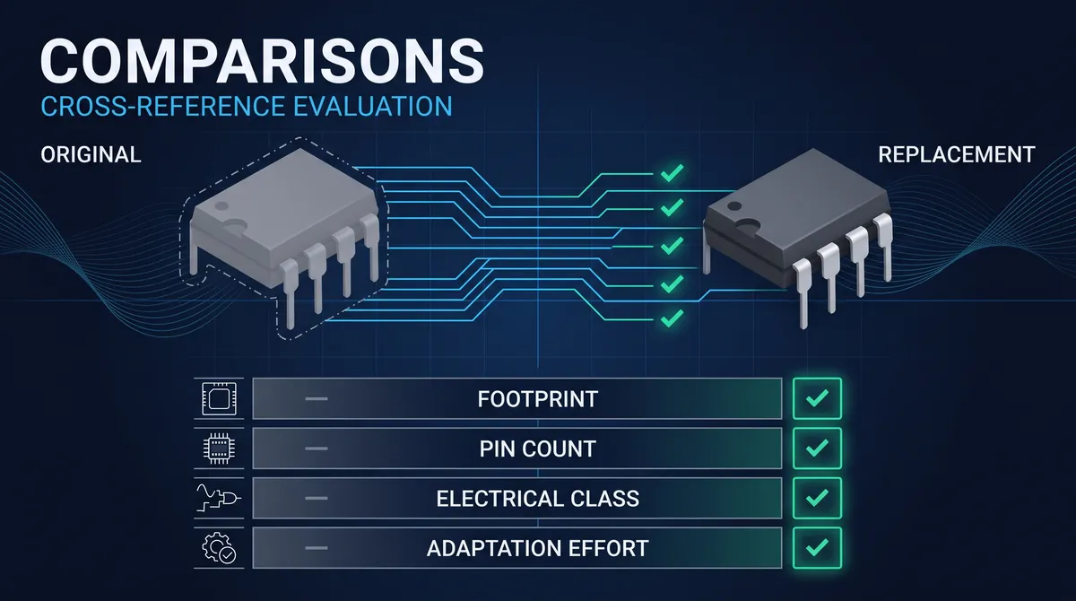
AMS1117 vs LM1117 is a comparison that every designer of a 3.3-volt rail makes, because the two parts are the most common low-dropout regulators on the world's boards and on the countless modules of the electronics market. The LM1117 is Texas Instruments' 3-pin LDO, the adjustable or fixed low-dropout regulator rated for the 800-milliamp range, a part with a decades-long history in the original National Semiconductor line. The AMS1117 is the Advanced Monolithic Systems LDO, a similar 3-pin part rated for the 1-amp range, and it is the part behind the ubiquitous cheap 3.3-volt modules that fill the hobby and the production channels. The two share the SOT-223 footprint and much of the pinout, which is why the comparison is so common, and they differ in the current rating, the dropout in practice, and the supply story that this guide reads honestly. This guide compares the two across the package, the current, the dropout, the quality, the cost, and the applications, and it gives the rule for choosing between them, including the community's well-known cautions about the AMS1117.
The comparison is also honest in a way the market rarely is, because the AMS1117's popularity has brought its quality into question and the community has spent years debating it. The reddit and the eevblog threads that this comparison often surfaces ask how reliable the AMS1117 really is, why the cheap modules fail, and whether the 1117 family is even the right choice for a new design, and the answers deserve a straight treatment. This guide gives that treatment, the engineering comparison of the two parts and the honest account of the AMS1117's reputation, its failures, and the caution it has earned, so that a designer chooses between the LM1117 and the AMS1117 on the evidence rather than on the price alone, and considers the modern LDOs that have moved past the whole family.
AMS1117 vs LM1117: The Core Comparison
The AMS1117 and the LM1117 are both 3-pin, low-dropout, adjustable-or-fixed linear regulators, and the core comparison is a difference of current, heritage, and supply rather than of architecture. Both parts regulate a positive output from a slightly higher input, both are available in fixed versions such as the 3.3-volt and the 5-volt and in the adjustable version set by a resistor divider, and both carry the classic LDO dropout of roughly a volt or more in the practical range. The differences are the rating and the source: the LM1117 is rated in the 800-milliamp class and comes from the TI line with the mature datasheet and the long history, while the AMS1117 is rated at the 1-amp class and comes from the AMS line, and it is the part that the price-driven modules standardized on. The two parts are not the same silicon under two names, they are two implementations of the same 1117-style LDO family, and the comparison reads the family's shared character and the two parts' different supply stories.
The design that needs a 3.3-volt rail for a few hundred milliamps can use either part, and the comparison then turns on the details: the current margin, the dropout at the operating point, the package and the pinout on the board, the quality of the specific units, and the cost. The two parts also share the SOT-223 footprint in their most common form, which is the fact that makes the comparison practical, because a board laid out for one generally mounts the other, and the swap is a sourcing decision rather than a layout decision. The guide therefore walks the comparison in that order, the shared family, the current and the dropout, the pinout, the quality, and the applications, and it closes with the supply view, so that a designer reads the AMS1117 vs LM1117 decision as the multi-factored call it really is.
The 1117 LDO family and where the two parts sit
The 1117 family is a 3-pin positive LDO family with a large place in electronics history, and the LM1117 and the AMS1117 sit at its two ends. The family traces from the National Semiconductor LM1117, an adjustable and fixed low-dropout regulator in the SOT-223 and related packages, and the industry reproduced it across the vendors, with the AMS1117 being the most widely copied implementation, especially in the Chinese electronics ecosystem where the cheap modules are made. The family's defining numbers are its low drop for its era, the adjustable and the fixed output options, and the SOT-223 and TO-252 packages, and those numbers made the 1117 the default 3.3-volt and 5-volt LDO for an enormous generation of boards. The LM1117 and the AMS1117 both carry the family's DNA, and the comparison between them is a comparison within the family, the TI original against the market's most common copy, which is why the two names appear together in every 1117 discussion.
Current Rating and Dropout: AMS1117 vs LM1117
The current rating is the first number the comparison reads, and it is where the two parts differ on the datasheet. The LM1117 is rated in the 800-milliamp class by TI, and the AMS1117 is rated at the 1-amp class by AMS, so the AMS1117's headline number is larger, but the practical reading is more careful than the headline. Both parts derate with the heat, and the dropout of the whole family is the real limit: an 1117-style part drops roughly a volt at the moderate current and more at the high end, so a 3.3-volt rail from a 5-volt input carries about 1.7 volts of headroom against a 1-volt-plus dropout, and the heat is the price of the higher current. The current the board can actually draw is set by the junction temperature, the SOT-223's thermal path, and the board copper, rather than by the labels, and a design that runs an 1117 near its limit widens the gap between the datasheet and the reality. The current comparison is therefore a reading of the margin, the dropout, and the thermal together, and the AMS1117's higher headline does not automatically mean a higher usable load.
The dropout deserves its own honest read, because the 1117 family's dropout is the specification that the community's caution centers on. The datasheet dropout in the tens to a few hundred millivolts at light current rises to the volt class at the high current, and the practical dropout of the cheap AMS1117 units can exceed even that, which is one of the reasons the threads ask how reliable the part is. The name low-dropout is true relative to the earlier regulators, but a modern LDO drops a few hundred millivolts at its rated current, and the 1117's volt-class dropout is no longer the low-drop standard, which is why the community tells designers not to use 1117 parts in new designs when the headroom is tight. The dropout read is the family's honest weakness, and the comparison presents it plainly rather than polishing it, because the designer who knows the dropout before the layout protects the rail from the sag at the load step.
Why a 1-amp LDO may not deliver 1 amp in practice
A 1-amp rated LDO often does not deliver 1 amp in practice, and the reasons are the heat and the dropout. The dissipated power is the input-minus-output difference times the current, so a 3.3-volt rail from a 5-volt input at 1 amp burns about 1.7 watts, and a SOT-223 in still air sheds only a fraction of that before the junction exceeds its rating, so the usable current at the 1-amp label is a fraction of the label without the board copper and the airflow. The dropout at the high current adds to the requirement, and a part whose dropout grows past the headroom at the load current drops out and follows its input. The practical reading is to derate the 1117, the AMS1117 and the LM1117 alike, to the few-hundred-milliamp range for the SOT-223, and to design the copper and the enclosure for the watts if the rail must run hot. The 1-amp label is the absolute limit, not the operating point, and the designer who reads the thermal before the rail reads the part's real rating.
Pinout and Package: Are the AMS1117 and LM1117 Interchangeable
The package and the pinout are the practical half of the comparison, and the SOT-223 footprint is why the two parts are so often swapped. Both parts ship in the SOT-223, the 3-lead surface-mount package with the large tab, and the pin positions and the tab follow the family's convention in the common versions, so a board laid out for the LM1117's SOT-223 generally accepts the AMS1117's SOT-223, and the reverse. The swap is not automatic, because the pinout must be verified against the exact variant and the package, but the family's standardization is the reason the AMS1117 and the LM1117 appear in the same boards and the same modules, and the reason the comparison is a sourcing question rather than a layout question for the board that uses the standard SOT-223. The footprint is the physical bridge between the two parts, and the bridge is the first fact the comparison states.
The caution that comes with the pinout is the verification rule, because the 1117 family has its variants and the specifications can differ by the vendor. The designer verifies the pin order, the input, the output, and the adjustable or the ground pin, against the datasheet of the exact part and the exact package, before trusting the swap, and verifies the tab connection, because the tab carries the output in the common SOT-223 and the thermal path in every package. The TO-252 and the other package versions carry their own pinouts, and the board that uses a non-SOT-223 package verifies that package separately. The interchangeability is real within the standard SOT-223, and the verification is the small discipline that keeps it safe, because the family's sameness is a strong rule with a need for a glance at the datasheet.
The SOT-223 footprint and the drop-in question
The SOT-223 footprint makes the drop-in question practical, because both parts sit on the same 3-lead surface-mount pad with the large tab. The footprint is a standard 4-pad pattern, the three leads and the tab, and the AMS1117 and the LM1117 in their common SOT-223 forms lay the input, the output, and the adjustable-or-ground pin in the same order on those pads, so the board accepts both and the reflow follows the same profile. The drop-in is real for the board that picked the standard SOT-223 form, and it is the reason a designer can evaluate the two parts on the same board and a buyer can source either. The drop-in is not a promise, it is a convention, and the convention holds for the standard form and is verified for the variant, which is the honest way to state the SOT-223 interchangeability. The footprint is the bridge, and the verification is the toll.
Quality, Cost, and Reliability: The AMS1117 Debate
The AMS1117's reputation is the most contested ground of the comparison, and the honest account is that the part's reliability varies with the source and the design far more than the LM1117's. The AMS1117 is the part behind the cheapest 3.3-volt modules, and the quality of those modules and the parts inside them spans a wide range, from the decent AMS-produced units to the indistinguishable copies that the price races to produce, and the difference shows in the dropout, the stability, and the failures the community reports. The LM1117 from TI carries the mature process and the documented quality, and its price is higher, and the extra cost buys the consistency that the commodity AMS1117 channel does not guarantee. The debate is real, and the fair summary is that the LM1117 purchases the quality and the AMS1117 purchases the price, with the reliability of any specific AMS1117 lot depending on the source, which is why the verification of the AMS1117 is the buyer's responsibility.
The reliability findings the community reports deserve a straight account, because they shape the choice. The threads and the failure reports describe the AMS1117 failing under the heat, the parts that drop out early, the modules that die under load, and the parts whose dropout and stability drift from the datasheet, and the common theme is the price-driven source rather than the design itself, because an AMS1117 run from a genuine AMS or a qualified supplier behaves differently from an indistinguishable copy from a no-name source. The engineer's response is to treat the AMS1117 like any commodity part and verify the source, test the lot, and derate the design, and the buyer's response is to expect that the cheapest unit carries the risk. The comparison states this honestly, because a designer who knows the AMS1117's reputation sources it like the commodity it is and reserves the LM1117 for the rail that must be right.
How to tell a good AMS1117 from a bad one
Telling a good AMS1117 from a bad one is the verification discipline that the commodity channel demands, and it runs on the inspection the series has covered. Buy from a source that can identify the real manufacturer and the lot, and verify the part against the real AMS or the qualified supplier's marking, because the copies reuse the marking and the grain of the quality is in the source. Test the lot, the dropout at the load, the regulation, the current, and the temperature behavior, against the datasheet and the design's rail, because a good AMS1117 holds the spec and a weak copy drifts under the load. Derate the design, keep the current well below the 1-amp label, keep the headroom against the dropout, and sink the heat, because the SOT-223's thermal reality applies to the good part as well as the bad. And the second source, keep the LM1117 or a qualified alternative as the fallback for the rail that the commodity part must not fail. The discipline is the same for any commodity part, and the AMS1117 earns it by its place in the price race, which is the honest verdict of the debate.
When to Choose the LM1117
Choose the LM1117 when the rail has to be right, because the TI part carries the mature process, the documented quality, and the consistent supply that a production rail benefits from. Choose it for the boards that the reliability matters on, the products that ship, the rails that the consumer or the customer touches, and the designs where the difference between a clean vendor and a commodity copy is worth the price. Choose it when the design wants the datasheet to describe the part, the dropout, the thermal, and the application curves that the TI document provides, because the documentation is part of the part. The LM1117 is the answer to the quality-first rail, and the comparison's rule is to let the TI part own the rail that must be right.
The 1117 choice also carries the sourcing depth, because the LM1117 and its family have been produced for decades and the replacement market is deep. The pin-compatible equivalents, the vendor variants, and the domestic parts that copy the family cover the sourcing, and the verification is the same discipline that this site's guides apply everywhere. The LM1117's story is the mature 3.3-volt rail and the documented quality, and the guide's view matches, the right part for the rail that matters, with the deep family behind it.
When to Choose the AMS1117
Choose the AMS1117 when the million-unit price and the ubiquity win the design, because the AMS1117 is the cheapest credible 3.3-volt LDO and the easiest to source from the Chinese ecosystem at volume. Choose it for the cost-driven boards, the modules, the hobby designs, and the products where the rail is a few hundred milliamps and the risk is acceptable against the price, and choose it when the source is qualified, the lot is tested, and the design derates the part the way the commodity deserves. The AMS1117 is the answer to the cost-first rail, and the comparison's rule is to let the affordability own the rail where the engineering accepts the commodity risk.
The 1117 choice also reads the responsibility, because choosing the AMS1117 is choosing to manage a commodity. The buyer qualifies the source, the real manufacturer, the lot, and the test, and the engineer derates the current, the headroom, and the heat, and the design verifies the part on the board before production. The AMS1117's story is the price-competitive rail with the buyer's verification as the price of the bargain, and the guide states it plainly: the part is a fine choice when it is sourced and tested like the commodity it is, and a risky one when it is bought as the cheapest number on a listing. The AMS1117 keeps its place in the market because the market's volumes are real, and the designer who treats it honestly gets the price without being burned by the unknown copy.
Designing a 3.3-Volt Rail with a 1117 LDO
Designing a 3.3-volt rail with a 1117 LDO is the worked example that turns the datasheet numbers into a board, and the arithmetic shows why the family is both popular and derated. Take the common rail, a 5-volt input and a 3.3-volt 500-milliamp output. The throughput check is the dropout: at 500 milliamp the 1117 family's dropout is in the volt class, about 1.1 to 1.2 volts on a good unit, and the headroom is the input minus the output, about 1.7 volts, so the 5-volt input clears the dropout with margin, and the rail regulates. The thermal check is the real limit: the dissipated power is the input-minus-output difference times the current, 1.7 volts times 0.5 amp, about 0.85 watt, and the SOT-223's junction-to-ambient resistance in the 50-to-90-degree-per-watt class, depending on the board copper, puts the junction at 25 degrees ambient plus 0.85 times the resistance, cold on the generous copper and approaching the 125-degree rating on the small pad. The arithmetic is the reason the 800-milliamp and 1-amp labels derate to the few-hundred-milliamp reality on a SOT-223 at a 1.7-volt drop, which is the honest behavior behind the datasheet's absorption-maximum table.
The same worked example also shows the capacitor and the layout decisions that complete the rail. The input needs a capacitor in the 10-microfarad class placed close to the input pin, to handle the source impedance and the load transients, and the output needs a capacitor in the 22-microfarad class with the low ESR that the datasheet recommends, because the 1117's stability depends on the output capacitor's ESR window, and the recommended tantalum or the low-ESR electrolytic lands inside it. The adjustable version replaces the fixed output with the resistor divider that sets the output from the 1.25-volt reference, and the divider's tolerance joins the output tolerance. The layout keeps the input and the output capacitors at the pin, the trace from the sense point short, and the ground quiet, which is the same discipline the fixed and the adjustable versions both need. The worked example is the path from the datasheet to the rail, and it is the path that the AMS1117 and the LM1117, the fixed and the adjustable, all follow on the same SOT-223 footprint.
The 5-volt to 3.3-volt thermal calculation
The thermal calculation for the 5-volt-to-3.3-volt rail deserves the numbers, because it is the number that decides the usable current. At a 0.5-amp load the dissipation is 0.85 watt, and at a 1-amp load it is 1.7 watts, since both scale by the same 1.7-volt drop. The SOT-223's junction-to-ambient resistance is the variable: on a minimal pad in still air it can sit near 80 degrees per watt, which puts the 1-amp dissipation at a junction near 25 plus 136 degrees, over the 125-degree rating, while the 0.5-amp dissipation at the same resistance lands near 25 plus 68, about 93 degrees, inside the rating but warm. The generous board copper that the SOIC-223's pad ties to can halve the resistance, so the same 1-amp part runs near 60 to 70 degrees on the copper-rich board, which is why the actual usable current varies so widely with the layout. The design reads the number at its own current, its own ambient, and its own copper, rather than from the label, and it keeps the margin that the datasheet's thermal model shows. The calculation is the working face of the "1 amp" that the AMS1117 and the LM1117 labels both carry, and it is the number the thermal design uses.
Measuring Dropout and Regulation on the Bench
Measuring the dropout and the regulation of a 1117 on the bench is a procedure that separates the good unit from the weak one, and it is the verification the AMS1117's reputation makes necessary. Set up a variable bench supply on the input, an electronic load on the output, and a multimeter across the output, then measure the dropout: set the load current, reduce the input until the output sags a defined amount, typically 100 millivolts below the nominal, and read the input at that point, and the dropout is the input minus the output. Sweep the current from a few milliamps to the rating and record the dropout curve, because a good 1117 holds the volt-class dropout across the range and a weak copy rises faster and slumps earlier. Measure the load regulation next, holding the input and stepping the load from zero to the rating and recording the output change, and measure the line regulation, holding the load and stepping the input, and the two numbers state how well the part holds the rail. The measurements on a real LM1117 and on a cheap AMS1117 often tell the story the datasheets do not, the cheap unit's dropout higher and its regulation looser at the current, which is the difference that the source verification in this guide is meant to catch.
The bench measurement also confirms the exact rail the board needs, because the datasheet's numbers and the board's reality differ in the margins. Mount the candidate on the board that will ship and measure the output at the design's worst-case load and input, the sag under the load step, the ripple into the load, and the behavior at the temperature the product sees, and compare the results against the rail's specification. The measurement at the operating point is the referee of the whole selection, because a part that passes the datasheet reading and fails the board's worst case is a part the design cannot trust, and the record of the measurement is the evidence the change doc carries. The bench procedure is the same for the fixed and the adjustable versions, with the divider's tolerance read into the adjustable one's accuracy, and it is the procedure that turns the AMS1117 versus LM1117 choice from a label into a measured decision. The measurement is the honest completion of the datasheet, and it is the completion the rail's reliability depends on.
The Failure Modes of an 1117 and What They Look Like
The 1117's failure modes are the named symptoms behind the community's caution, and recognizing them tells a designer where the fault lives. The first and most common is the thermal shutdown, which happens when the dissipated power, the drop times the current, pushes the junction over its rating, and the part's thermal protection cycles the output, so the rail browns out in a regular on-off pulse that the oscilloscope shows as the sawtooth melt-down, and the fix is the lower current, the lower drop, or the better thermal path. The second is the loss of regulation, which happens when the input sags toward the output plus the dropout, and the output follows the input, so a 3.3-volt rail that should hold reads below nominal and the ripple tracks the source, and the fix is the headroom or the LDO with a lower dropout. The third is the oscillation, which happens when the output capacitor's ESR sits outside the stability window or the wiring is too long, and the output shows a high-frequency ripple or a low-frequency wiggle that the scope reveals, and the fix is the correct capacitor and the short traces. The fourth is the sag under the load step, which happens when the current approaches the part's real limit and the dropout eats the margin, and the rail dips on the step and recovers slowly, and the fix is the derating and the margin. Each mode has a signature and a fix, and the signature is what the bench measurement reads.
The failure modes also map to the AMS1117's reputation, because the cheap units fail in the thermal and the dropout modes more often than the rated parts, and the reports in the community are the same symptoms this guide names. The module that dies under the load, the output that drifts, and the part that could not deliver its label are the thermal and the dropout modes at work, and the common cause is the price-driven source and the marginal design rather than the family itself, because a genuine AMS1117 run within its real derating behaves like the part it is. The engineer's response is to derate, to verify the lot, and to keep the headroom, and the buyer's response is to source the part from a source that can name the real manufacturer, which is the discipline the debate section laid out. The failure modes are the diagnostic side of the AMS1117 versus LM1117 comparison, and reading them keeps a rail from dying silently in the field, which is the practical value of the diagnostic half of this guide.
The Input and Output Capacitors: Sizing for Stability
The capacitor sizing for an 1117 is the small detail that the datasheet states and the field forgets, and it decides the rail's stability. The 1117's hold a stable output depends on the output capacitor's ESR, because the internal compensation assumes a capacitor in a defined ESR window, and the datasheet's recommended output capacitor, a low-ESR tantalum or a low-ESR electrolytic in the 10-to-22-microfarad class, lands the ESR inside the window, while a capacitor with the ESR too low or too high can push the part into the oscillation that the failure modes section described. The modern ceramic output capacitors are the wrinkle, because their ESR is far below the traditional window and the 1117's older compensation may not accept them, though many of the newer and the copied parts are ceramic-tolerant, so the designer reads the specific datasheet's stability statement before choosing the output cap. The input capacitor is the simpler choice, a 10-microfarad class electrolytic placed close to the input pin to hold the source impedance and the transients, and the ceramic input capacitor adds the high-frequency bypass. The capacitor read is the stability half of the rail, and it is the half that the layout and the bill of materials both carry.
The capacitor sizing also reads the derating that the ceramic parts carry, because the value on the label is not the value at the bus. A 22-microfarad X5R ceramic at 3.3 volts and the DC bias of the rail delivers a fraction of its rated capacitance, sometimes half or less, because the ceramic's capacitance collapses as the applied voltage rises, so the effective value at the rail is what the stability sees, not the label. The designer reads the capacitor's DC-bias curve from its datasheet, sizes the ceramic for the effective value, or uses the tantalum whose capacitance stays near the label. The adjust pin of the adjustable version also wants its small bypass capacitor where the datasheet recommends it, to keep the reference quiet. The tantalum holds its value and its ESR window at the cost of a higher price and a scarcity history, while the ceramic is cheaper and more available but delivers the derated value and the low ESR that the part's stability must accept, so the choice between them is a price-and-stability trade that the specific datasheet resolves. The capacitor and the derating reads complete the rail design, and they are the detail that keeps the 1117 running quietly on the board, which is the practical finish of the worked example in this guide.
The Modern LDO Question and the Alternatives
The AMS1117 vs LM1117 comparison is also a question about the family's place, because the modern LDOs have moved past the 1117's limits and the community's "stop using 1117 in new designs" threads point to them. A modern low-dropout regulator drops a few hundred millivolts at its rated current, where the 1117 family drops a volt class at its high end, and the modern parts bring the lower quiescent current, the better stability, and the better thermal behavior that the newer process provides. A design that runs the 3.3-volt rail from a 5-volt bus with a tight headroom reads the modern LDO instead of the 1117, and a design that needs the low inactive current for the battery reads a modern quiescent-current part. The 1117 family remains the right choice for the boards and the rails that already use it, and the guide's honest note is that a new design should check the modern LDOs before defaulting to the 1117, because the family that filled the world's 3.3-volt rails is no longer the low-drop or the low-current standard.
The alternative view also runs the replacement and the sourcing, because the modern LDOs and the 1117's pin-compatible kin both belong to the supply. A board that must keep its SOT-223 footprint can source the LM1117, the AMS1117 from a qualified source, or a domestic 1117-family part, and a board that can change its footprint read the modern LDOs that serve the same 3.3-volt rail better. The comparison therefore closes with the same method that the series has used: choose by the rail's requirement, verify the part and the source, and keep the replacement view, because the LDO's price, quality, and the supply story all live beside the datasheet. A designer who reads the AMS1117 vs LM1117 comparison this way chooses the part for the rail, the budget, and the verified source, and the choice is the working answer that the schematic and the board both accept.
Not sure which sensor fits your project?
Talk to our mmWave application engineers for a free consultation.
Specify your hotel project with our engineers
Send your room count, ceiling type, and protocol preference. We will return a sample plan and quote within 24 business hours.
- Move from general guidance into a product or application discussion.
- Use RFQ when pricing, drawings, MOQ, or launch timing needs structure.
- Keep a direct contact path visible for fast clarifications and handoff.